Nuclear magnetic resonance device

a nuclear magnetic resonance and device technology, applied in the direction of reradiation, magnetic variable regulation, instruments, etc., can solve the problems of malfunction or operating failure, the vibration isolation mechanism is unsuitable for the vibration isolation of the nuclear magnetic resonance apparatus, and the precision measurement cannot be performed by the apparatus,

Inactive Publication Date: 2006-09-14
RIKEN +1
View PDF7 Cites 9 Cited by
  • Summary
  • Abstract
  • Description
  • Claims
  • Application Information

AI Technical Summary

Benefits of technology

[0008] In order to achieve the above object, according to a first aspect of the present invention, there is provided a nuclear magnetic resonance apparatus comprising: a nuclear magnetic resonance means for elucidating an atom configuration and a molecular structure of a substance based on a decay signal of induced electromotive force caused by resonance precession of nuclear magnetic moment induced by irradiation of electromagnetic pulses in an RF region when a substance is exposed to a strong magnetic field; and a vibration isolation mechanism for suppressing vibration of this nuclear magnetic resonance means, wherein the vibration isolation mechanism has an air spring as an actuator, the air spring being connected to a pressurized air source via an electro-pneumatic converter and acting to exert a force for vibration isolation on the nuclear magnetic resonance means, and the vibration isolation mechanism is formed so as to be capable of active vibration isolation, and disposed away from the nuclear magnetic resonance means by such a distance that the electro-pneumatic converter never incurs any malfunctions or operating failures under influence of a magnetic field generated by the nuclear magnetic resonance means.
[0009] With this constitution, the leak magnetism from the nuclear magnetic resonance means is weakened in the vicinity of the electro-pneumatic converter, thus producing effects that the inherent performance of the vibration isolation mechanism can be fully obtained even under a strong magnetic field, the vibration is suppressed without incurring amplification of the vibration due to the resonance at the natural frequency, and that precision measurement can be performed.

Problems solved by technology

In the case of the apparatus described in the Japanese Patent Laid-Open publication No. 2001-145611 in which a passive-type vibration isolation mechanism is employed as the vibration isolation mechanism, since a vibration is amplified at around the natural frequency as described above, the vibration isolation mechanism is unsuitable for vibration isolation of a nuclear magnetic resonance apparatus which is a precision measuring instrument.
That is, in the case of the nuclear magnetic resonance apparatus using the passive type vibration mechanism, since the vibration of the apparatus causes side band noise in a nuclear magnetic spectrum responsive to a frequency of the vibration, such a problem arises that precision measurement can not be performed by the apparatus.
On the other hand, the aforementioned active type vibration isolation mechanism employs such a constituent element as a servo valve or a servo acceleration sensor which may lead to malfunctions or operating failures under the influence of external strong magnetic field.
Therefore, even if a nuclear magnetic resonance apparatus formed by applying this active type vibration isolation mechanism of the conventional type to the nuclear magnetic resonance means which is a source of a strong magnetic field, such a problem arises that the vibration isolation mechanism does not operate normally, with the result that it becomes impossible to perform precision measurement also by this nuclear magnetic resonance apparatus as in the foregoing case.

Method used


Image

  • Nuclear magnetic resonance device
  • Nuclear magnetic resonance device
  • Nuclear magnetic resonance device

Examples


Embodiment Construction

[0028] Hereinafter, embodiments of the present invention are described with reference to the drawings.

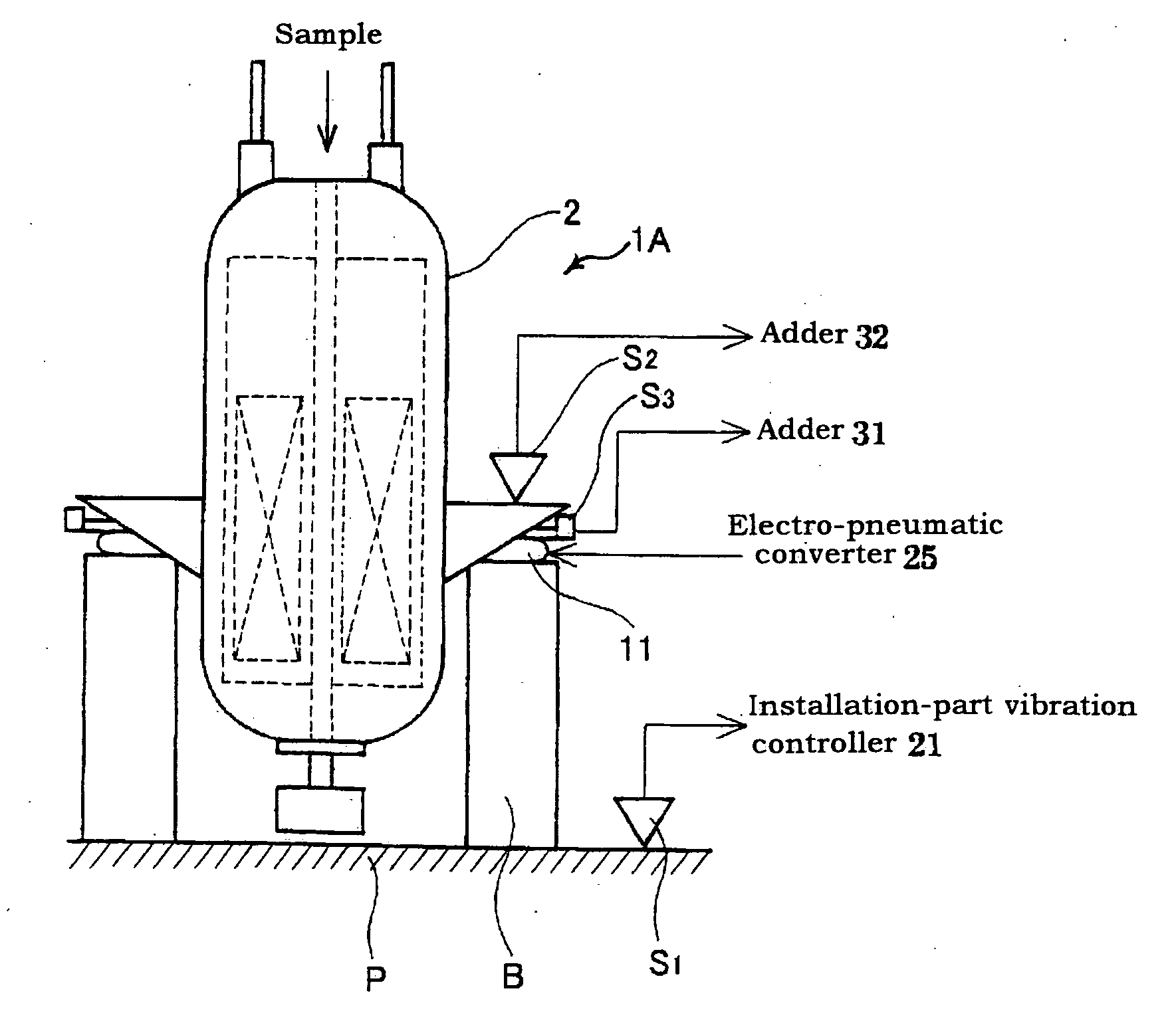
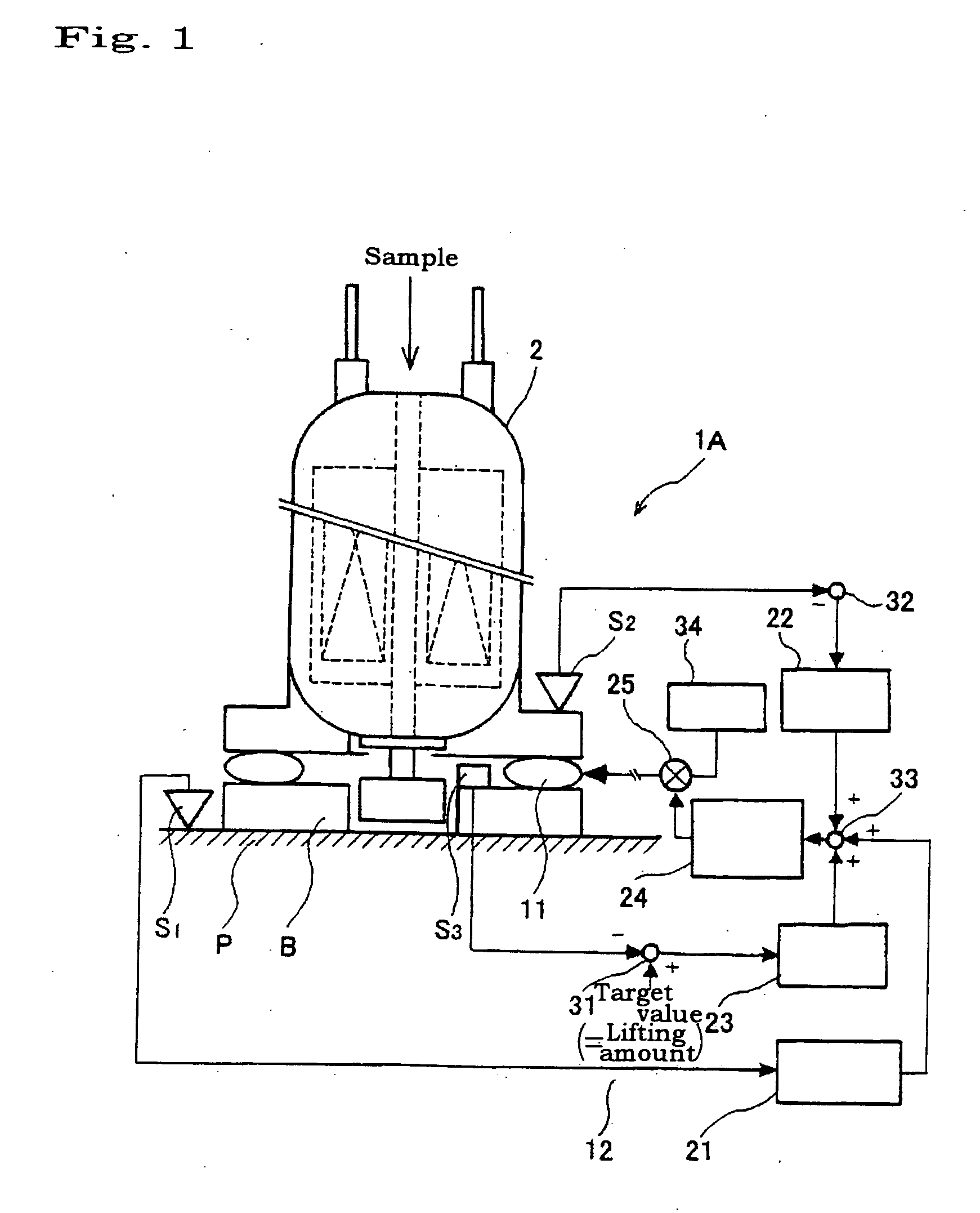
[0029]FIG. 1 shows a nuclear magnetic resonance apparatus 1A according to the present invention, and this nuclear magnetic resonance apparatus 1A is comprised of a nuclear magnetic resonance means 2 and a vibration isolation mechanism 3.

[0030] The nuclear magnetic resonance means 2, which is a well known one including a magnetic resonance imaging means, is intended to elucidate an atomic configuration and a molecular structure of a substance based on a decay signal of induced electromotive force caused by resonance precession of nuclear magnetic moment induced by irradiation of electromagnetic pulses in an RF region when the substance is exposed to a strong magnetic field.

[0031] The vibration isolation mechanism 3, which is provided for active vibration isolation of the nuclear magnetic resonance means 2, is comprised of an air spring 11 as an actuator and a control system 12 inc...


PUM


Abstract

In a nuclear magnetic resonance apparatus 1A including nuclear magnetic resonance means 2 for elucidating atomic configuration and molecular structure of a substance based on a decay signal of induced electromotive force caused by resonance precession of nuclear magnetic moment induced by irradiation of electromagnetic pulses in an RF region when the substance is exposed to a strong magnetic field, and a vibration isolation mechanism 3 for suppressing vibrations, the vibration isolation mechanism 3 has an air spring 11 as an actuator, the air spring being connected to a pressurized air source 34 via an electro-pneumatic converter 25 and acting to exert a force for vibration isolation on the nuclear magnetic resonance means 2, and the vibration isolation mechanism is formed so as to be capable of active vibration isolation, and disposed away from the nuclear magnetic resonance means 2 by such a distance that the electro-pneumatic converter 25 never incurs any malfunctions or operating failures under influence of a magnetic field generated by the nuclear magnetic resonance means 2.

Description

TECHNICAL FIELD [0001] The present invention relates to a nuclear magnetic resonance apparatus equipped with a vibration isolation mechanism. BACKGROUND ART [0002] Conventionally, a nuclear magnetic resonance apparatus has been known which comprises a nuclear magnetic resonance means for elucidating an atom configuration and a molecular structure of a substance based on a decay signal of induced electromotive force caused by resonance precession of nuclear magnetic moment induced by irradiation of electromagnetic pulses in an RF region when a substance is exposed to a strong magnetic field, and a vibration isolation mechanism for suppressing vibration of this nuclear magnetic resonance means (see e.g., Japanese Patent Laid-Open publication No. 2001-145611, paragraph [0011], FIG. 1). [0003] A vibration isolation mechanism itself of an active type using an air spring has also been known (see, e.g., “6DOF microvibration Control System using Air Actuators (Experimental Study on Vibratio...

Claims


Application Information

Patent Timeline
IPC IPC(8): G01V3/00G01R33/28
CPCG01R33/28
Inventor MAEDA, HIDEAKIYOKOYAMA, SHIGEYUKIYASUDA, MASASHIITOJIMA, FUMIAKITSUCHIYA, MASAKI
Owner RIKEN
Why Eureka
Try Eureka