Interrogator and interrogation system employing the same

a technology of interrogator and interrogator body, which is applied in the field of interrogator and interrogation system employing the same, can solve the problems of increasing mortality and morbidity risk, detention of valuable professional personnel, and errors in patient patient materials

Inactive Publication Date: 2006-09-14
LONE STAR SCM SYST LP
View PDF99 Cites 123 Cited by
  • Summary
  • Abstract
  • Description
  • Claims
  • Application Information

AI Technical Summary

Problems solved by technology

In common practice, access to and from an operating room in the surgical suite is restricted during the counting process thereby resulting in a detention of valuable professional personnel.
Thus, the multiple manual counting of surgical items is time consuming, ties up key professional personnel, contributes to surgical suite down time, distracts personnel from the surgical procedure, lengthens the time the patient is exposed to anesthesia leading to an increase in mortality and morbidity risk, is generally distasteful to all involved, and still results in errors wherein materials are left in the patient.
Even with the degree of caution cited above, the problem associated with the loss of surgical items, especially surgical items retained within patients, is a serious one and has a significant influence on the costs of malpractice insurance.
While this is generally effective, even these filaments are not 100% effective in aiding the location of the sponges.
Different researchers report that x-ray methods to supplement manual counting are fallible.
Moreover, in cases when a sponge remains in the body for a long time, the radiopaque filament can become difficult to locate and may even conform to internal structures.
As with bar coding, the RFID techniques are primarily used for automatic data capture and, to date, the technologies are generally not compatible with the counting of surgical items.
For surgical suites and for the purposes of counting surgical items, the medical community has rejected first generation inventory devices, such as bar coding and RFID techniques, because of a perception that the solutions have not been adapted to meet the stringent requirements of the surgical environment.
Contrary to popular understanding, however, the RFID tags including tags employing surface acoustical wave technologies may not suffer from many of the perceived limitations.
Moreover, the problems which hinder the use of bar coding in the surgical environment do not have the same implications for RFID tags.
This process exposes the item to be sterilized to high temperatures and is not suitable for materials which are affected by either moisture or high temperature such as corrodible and sharp-edged metals, plastic-made devices or other devices that may be employed in the medical environment.
While the x-ray procedure is difficult and expensive, the use of a radioactive source requires expensive waste disposal procedures, as well as radiation safety precautions.
The radiation techniques also present problems because of radiation-induced molecular changes of some materials which, for example, may render flexible materials such as catheters or bar coded labels brittle.
Very few identification techniques, labeling techniques or marking techniques are compatible with such a wide range of demanding conditions.
While a stainless steel instrument may be engraved with a form of a readable tag, such techniques are probably not compatible with disposable items such as sponges.
While identification tags or labels may be able to survive the difficult conditions associated with medical applications, there is yet another challenge directed to attaching an identification element to a surgical item.
While medical device manufacturers have multiple options for bonding, critical disparities between materials may exist in areas such as biocompatibility, bond strength, curing characteristics, flexibility and gap-filling capabilities.
Grasty, et al. and many other references teach that counting procedures are performed visually and there is little flexibility in tailoring the type and number of instruments for different procedures.
The computerized devices, however, are relatively complex and expensive such as the surgical count stand described in U.S. Pat. No. 4,943,939, entitled “Surgical Instrument Accounting Apparatus and Method,” to Hoover.
These systems suffer from a number of common shortcomings.
For instance, the currently available systems do not disclose an apparatus that automatically counts all types of surgical items, and the systems do not eliminate the time, financial costs, and risk associated with counting and recounting the surgical items to verify the specific identity and location of a missing item.

Method used


Image

  • Interrogator and interrogation system employing the same
  • Interrogator and interrogation system employing the same
  • Interrogator and interrogation system employing the same

Examples


Embodiment Construction

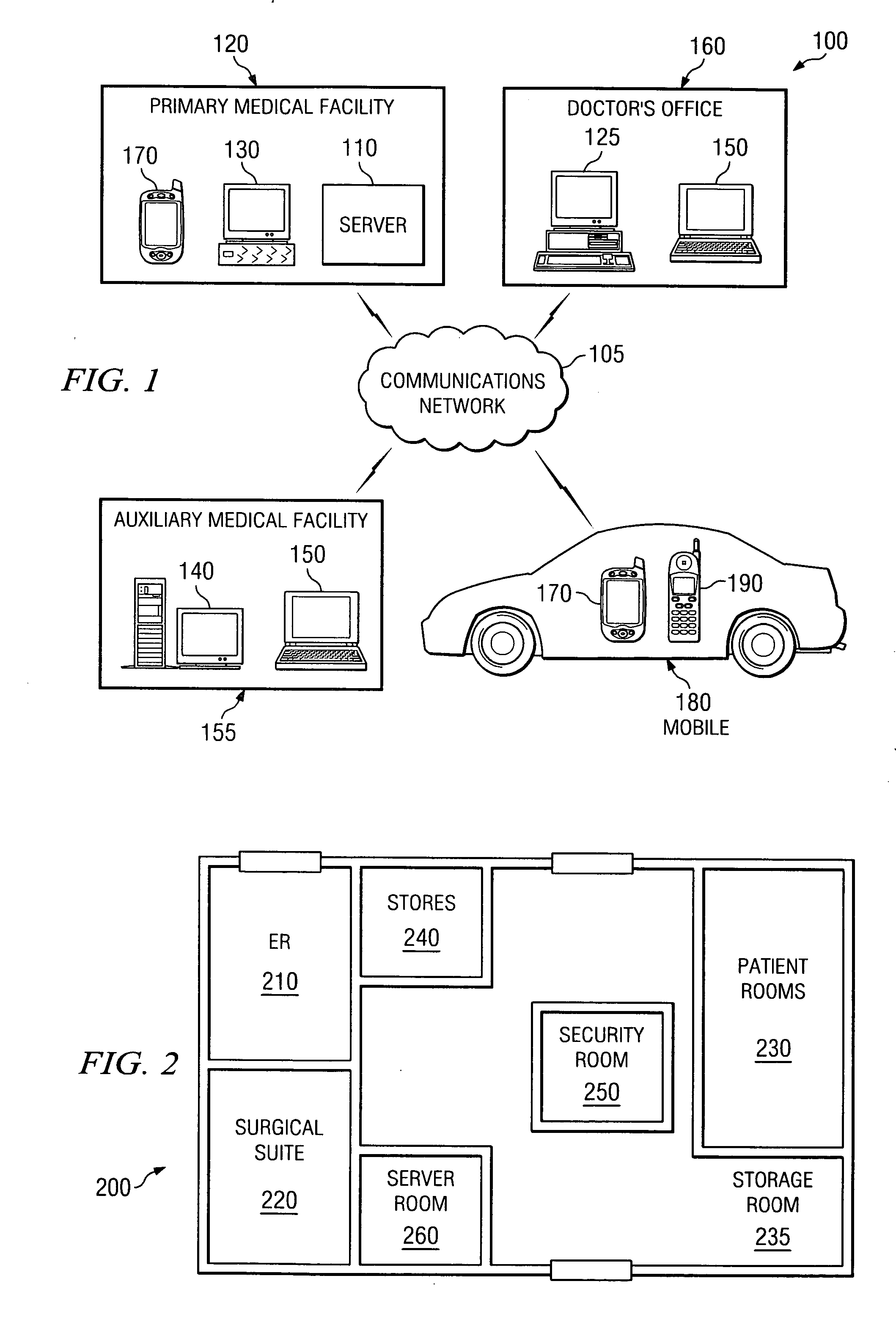
[0050] Referring initially to FIG. 1, illustrated is a diagram of an embodiment of a communication system, generally designated 100, employable in a medical environment constructed in accordance with the principles of the present invention. The communication system 100 is configured to distribute, collect and process information across a communications network 105 that may include a Local Area Network (LAN), a Wide Area Network (WAN), an Intranet, an Extranet, the Internet, the World Wide Web, the Public Switched Telephone Network (PSTN), future extensions of these (e.g., the Internet 2), or a combination thereof. For purposes of the present invention, the World Wide Web is defined as all the resources and users on the Internet that are generally using the Hypertext Transfer Protocol (HTTP). In one embodiment of the present invention, the communication system 100 communicates to each device connected thereto using Transmission Control Protocol / Internet Protocol (TCP / IP).

[0051] TCP / ...


PUM


Abstract

The present invention is directed to an interrogator, method of discerning metal and radio frequency identification (RFID) objects, and an interrogation system employing the same. In one embodiment, the interrogator includes a metal sensing subsystem configured to provide a first signal having a signature representing a presence of a metal object, and a RFID sensing subsystem configured to provide a second signal having a signature representing a presence of a RFID object. The interrogator also includes a control and processing subsystem configured to discern a presence of at least one of the metal and RFID objects from one of the first and second signals.

Description

[0001] This application is a continuation of patent application Ser. No. 10 / 378,043, entitled “Interrogator and Interrogation System Employing the Same,” filed on Mar. 3, 2003, which application is incorporated herein by reference.TECHNICAL FIELD OF THE INVENTION [0002] The present invention is directed, in general, to communication systems and, more specifically, to an interrogator, method of discerning metal and radio frequency identification (RFID) objects, and an interrogation system employing the same. BACKGROUND OF THE INVENTION [0003] Asset tracking for the purposes of inventory control or the like is employed in a multitude of industry sectors such as in the food industry, apparel markets and any number of manufacturing sectors, to name a few. In many instances, a bar coded tag or radio frequency identification (RFID) tag is affixed to the asset and a reader interrogates the item to read the tag and ultimately to account for the asset being tracked. Although not readily adop...

Claims


Application Information

Patent Timeline
Patent Type & Authority Applications(United States)
IPC IPC(8): G08B13/14G08B13/18G08B19/00G06K7/00G06K17/00
CPCG06K7/0008G06K17/00G06K2017/0045G06Q10/08G06Q10/087G06K7/10009G06K7/10316G06K7/10336G06K7/10386
Inventor VOLPI, JOHN P.LAFERNEY, JIMMY D.MONTGOMERY, WILLIAM C.
Owner LONE STAR SCM SYST LP
Why Eureka
Try Eureka