Medical examination or treatment apparatus

Inactive Publication Date: 2006-09-14
SIEMENS HEALTHCARE GMBH
View PDF10 Cites 18 Cited by
  • Summary
  • Abstract
  • Description
  • Claims
  • Application Information

AI Technical Summary

Benefits of technology

[0007] An object of the invention is therefore to improve the safe operation of medical examination or treatment apparatus that can be operated by means of mobile, wirelessly communicating operating elements.
[0009] According to the invention, there are proposed two equivalent options for improving the safety of the wireless operation of examination or treatment apparatus. According to the first alternative of the invention, the operating signals are deliberately modified or noisy so that, when the situation allows, only the assigned controlling system is activated but not the controlling system of adjacent examination or treatment apparatus disposed, for example, in another room. The direction-selective or frequency-selective device of this kind used can, for example, be a scrambler, which is preferably integrated into a building wall and operates in a direction-selective and / or frequency-selective manner such that operating signals generated on the near side of the building wall, after passing through the building wall, continue to be propagated in a modified state on the far side thereof, and thus no longer incorporate any control information that can lead to inadvertent incorrect actuation.
[0011] Conversely, in the second case, the operator is standing with operating element A in front of X-ray device B and wishes to activate said device using operating element A. Since the communication frequencies are normally within a relatively narrow bandwidth, as a rule it will not be possible to activate X-ray apparatus B using operating element A. Owing to the considerable radio transmission range, however, the operating signals may pass through the building wall and into the adjacent room in which apparatus A is disposed, and said signals may be received by the controlling system which activates the appropriate actuation of, for example, the image acquisition operation. This is naturally unintentional and can be advantageously prevented by the use of the one or more scramblers integrated into the building wall.
[0012] According to the second alternative of the invention, the operator is to be actively signaled to indicate whether or not he is standing in front of the controlling system assigned to the operating element. To this end, the examination or treatment apparatus is provided with at least one acoustic or visual signal transmitter, for example in the form of a tone generator or flashing light or the like. If the operator with the mobile operating element is standing in front of the assigned controlling system, that is to say, wishes to operate the “correct” apparatus, communication can be successfully set up between the operating element and the controlling system. If that is the case, the controlling system activates the acoustic / visual signal transmitter. The operator is therefore given an AF signal or a blinking signal which shows him that he is standing in front of the correct controlling system and can thus readily operate the apparatus. Were he to be standing in front of the wrong device, communication between the operating element and the controlling system could not be set up since, as a rule, these two have different communication frequencies. Thus it is also impossible for any acoustic / visual signal to be generated.

Problems solved by technology

The option of carrying the operating element from place to place, in particular in the case of a mobile hand-held device, poses the problem whereby the physician or operator may take the operating element with him and go into another room where there is likewise an X-ray device, for example, but one which would have to be operated with an assigned operating element of its own.
This means that mix-ups can occur over which operating element is to be used, possibly leading in turn to the unintentional actuation of functions.

Method used


Image

  • Medical examination or treatment apparatus
  • Medical examination or treatment apparatus
  • Medical examination or treatment apparatus

Examples


Embodiment Construction

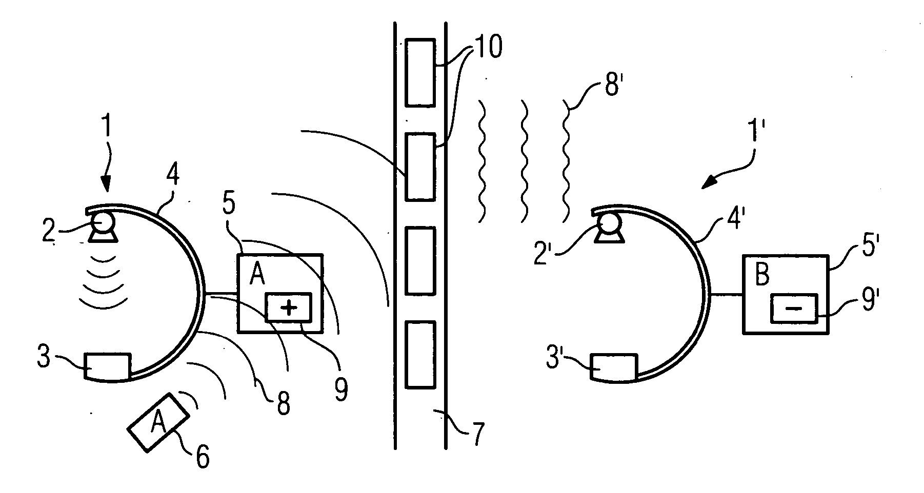
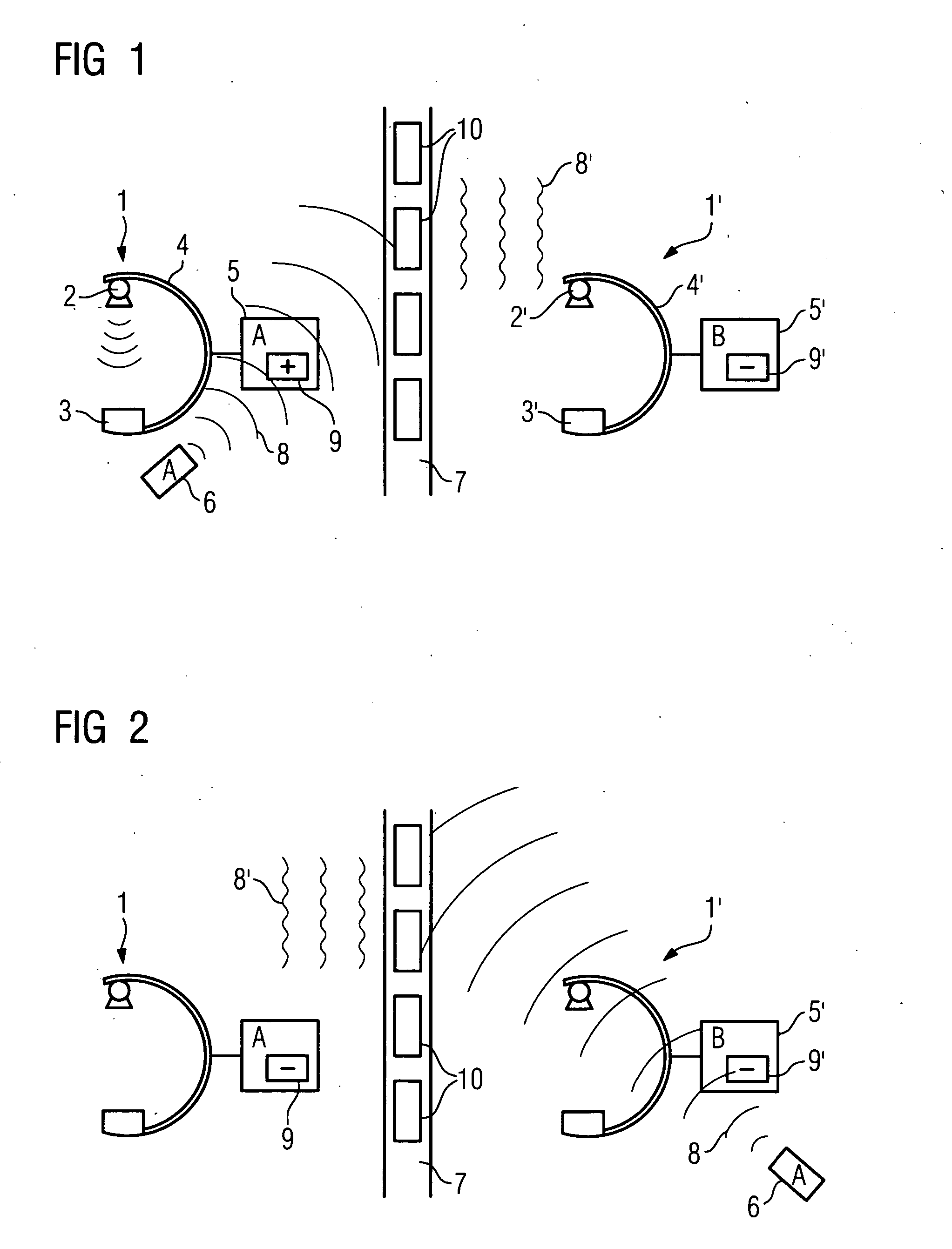
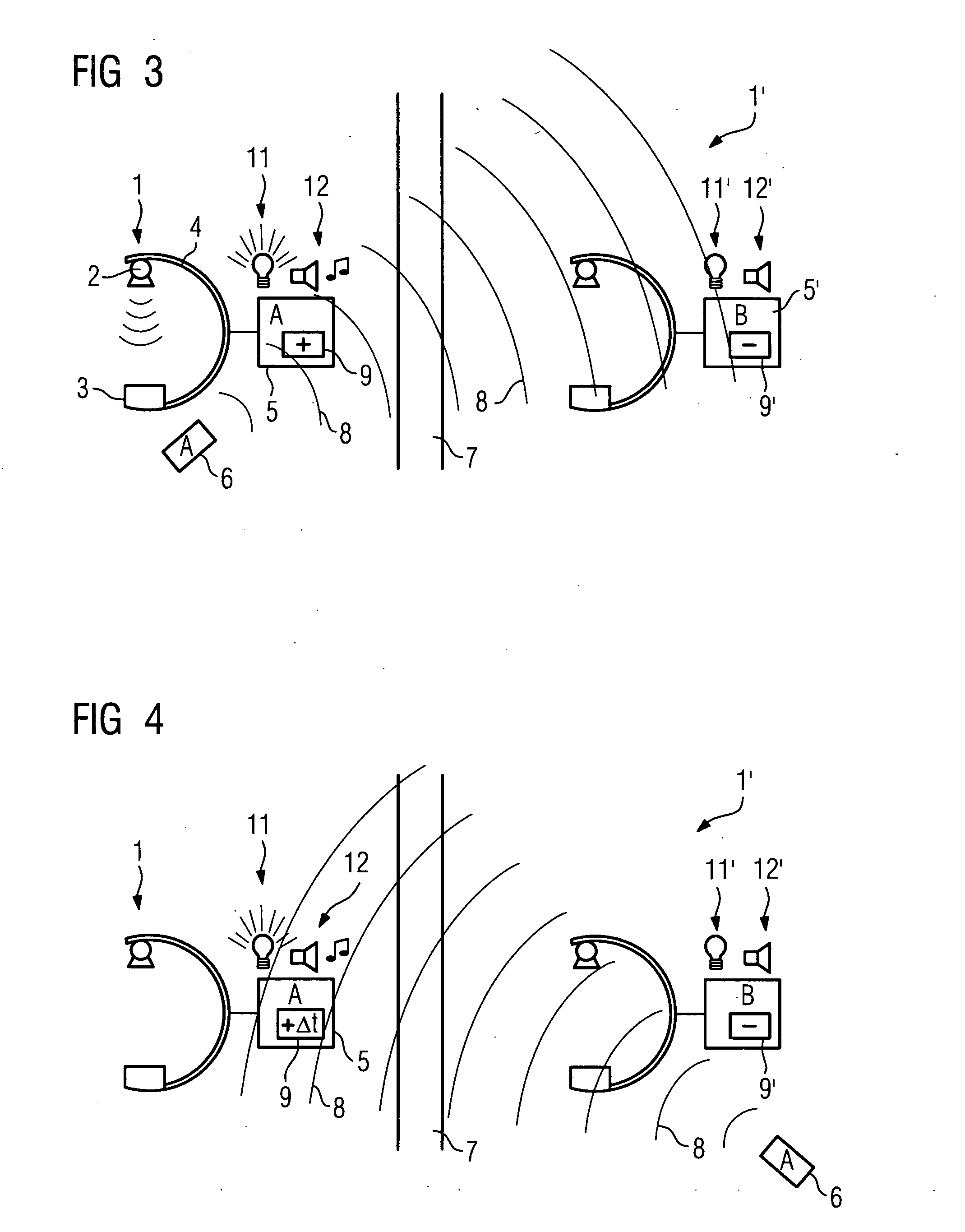
[0020]FIG. 1 shows first examination or treatment apparatus 1, in this case in the form of a C-arm X-ray device, comprising a source of radiation 2 and a radiation detector 3 which are disposed on a common C-arm 4. There is also an associated central controlling system 5. The structure of X-ray apparatus of this kind is sufficiently well known; FIG. 1 is merely a schematic sketch, and the individual components are not important.

[0021] Assigned to the controlling system 5 is a mobile operating element 6, for example a hand-held transmitter, which enables remote communication to take place with the controlling system 5 in order to actuate functions. The wireless communication can take place in any manner, for example by means of radio, Bluetooth, etc.

[0022] In an adjacent room, separated by a building wall 7, there is located further examination or treatment apparatus 1′, also shown here by way of example as X-ray apparatus, comprising a source of radiation 2′, a radiation detector ...


PUM


Abstract

Medical examination or treatment apparatus, in particular X-ray or CT apparatus, comprising a controlling system controlling the operation of one or more apparatus elements, and at least one mobile operating element which is assigned to the control-ling system and which communicates wirelessly with the control-ling system for operating the examination or treatment apparatus for the transmission of operating signals, there being pro-vided at least one device which operates in a direction-selective and / or frequency-selective manner to modify the operating signals transmitted by the operating element such that a controlling system of examination or treatment apparatus disposed adjacent the examination or treatment apparatus to be intentionally operated is not activated by the modified operating signals or there being provided on the examination or treatment apparatus assigned to the operating element at least one acoustic and / or visual signal transmitter which is actuated when an operating signal is generated by the assigned operating element.

Description

CROSS REFERENCE TO RELATED APPLICATIONS [0001] This application claims priority to the German Application No. 10 2005 011 667.1, filed Mar. 14, 2005 which is incorporated by reference herein in its entirety. FIELD OF INVENTION [0002] The invention relates to medical examination or treatment apparatus, in particular X-ray or CT apparatus, comprising a controlling system controlling the operation of one or more apparatus elements, and at least one mobile operating element which is assigned to the controlling system and which communicates wirelessly with the controlling system for operating the examination or treatment apparatus for the transmission of operating signals. BACKGROUND OF INVENTION [0003] Conventional examination or treatment apparatus, for example an X-ray system, consists of a plurality of spatially separate components such as a patient positioning table, an X-ray source ceiling stand and / or an X-ray source floor stand and a wall stand or a C-arm. Conventionally provided...

Claims


Application Information

Patent Timeline
IPC IPC(8): G01B9/02
CPCA61B6/00A61B6/467A61B6/548
Inventor REGN, JUDITHSTAAB, REINER
Owner SIEMENS HEALTHCARE GMBH
Why Eureka
Try Eureka