Method and apparatus for adjustable cutting of filamentary material

Inactive Publication Date: 2007-04-26
BILLINGSLEY JOHN G S
View PDF30 Cites 4 Cited by
  • Summary
  • Abstract
  • Description
  • Claims
  • Application Information

AI Technical Summary

Benefits of technology

[0011] The current invention provides a simplified means for directing continuous lengths of film and / or fiber through a transport tube into a rotating cutter and, uniquely, of adjusting the clearance between the stationary cutting surface and the moving knife or knives to provide optimum cutting conditions while the cutting machine is in the operating mode The stationary cutting surface, because of the versatility inherent in the design, can range from a transport tube to a cutting surface fixed at some chord within the transport tube. The design avoids the need for the heavy and expensive apparatus of U.S. Pat. No. 3,119,294, while functionally achieving improved operating flexibility and equivalent cutting capability at much lower cost. Air is drawn through the transport tube by a suitable suction device to align the continuous lengths of fiber or film within the transport tube to the point of cutting where one or more rotating blades traverse the exit end of the tube at high speed to cut the exiting filament, tape or film into suitable lengths, and to convey the cut material to some collection point.
[0014] The insert in the tube, or the tube itself may be oriented about the axis of the tube so that the anvil portion of the insert at the tube exit may be angularly adjusted relative to the leading edge of the blade passing over the anvil. It has been found that having an approach angle between the upper surface of the anvil in the tube insert or of the non-tapered portion of the transport tube, and the leading edge of the cutter blades improves cutting. This angling of the stationary cutting surface to the moving cutter blades reduces the amount of filament, tape or film being cut at any one time, thereby achieving both a reduced cutting load and a significantly lower cutting noise.
[0016] This simple, but effective, fine adjustment arrangement facilitates ready operation of the disclosed cutting system by relatively unskilled operators The operator need only rotate the adjustment ring a small amount to accommodate erosion of the cutting surface on or in the tube. This easy adjustment facilitates an empirical evaluation of the cutting as it takes place, i.e., the adjustment ring can be rotated thereby advancing the tube in a direction toward the blades until a suitable cut fiber or film exits the tube. In addition, the tube, with or without an insert, can be incrementally advanced toward the rotating blades to shave microscopically thin slices of material from the edge of the insert or of the tube, thereby removing the eroded or worn surfaces of that edge This re-establishes a sharp cutting edge and the close cutting clearance deemed best for effective cutting of the material

Problems solved by technology

That mechanism, however, is a very complex piece of machinery with expensive precision parts that are costly and requires substantial expertise to adjust.
There is no disclosure of means for adjusting the length of cut fibers or apparatus associated with the cutting blades to adjust the length of the cut fiber.
This arrangement tends to create a lot of high frequency noise as the air stream exiting the venture tube is repeatedly interrupted

Method used


Image

  • Method and apparatus for adjustable cutting of filamentary material
  • Method and apparatus for adjustable cutting of filamentary material
  • Method and apparatus for adjustable cutting of filamentary material

Examples


Embodiment Construction

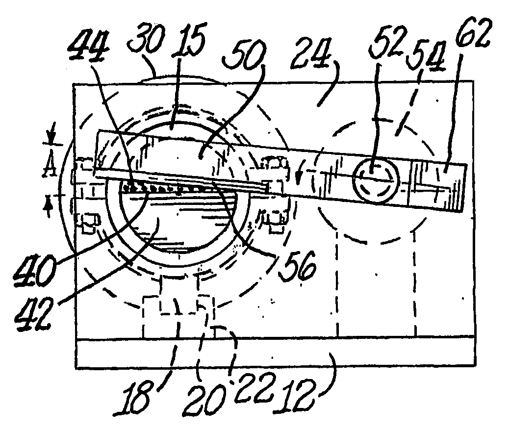
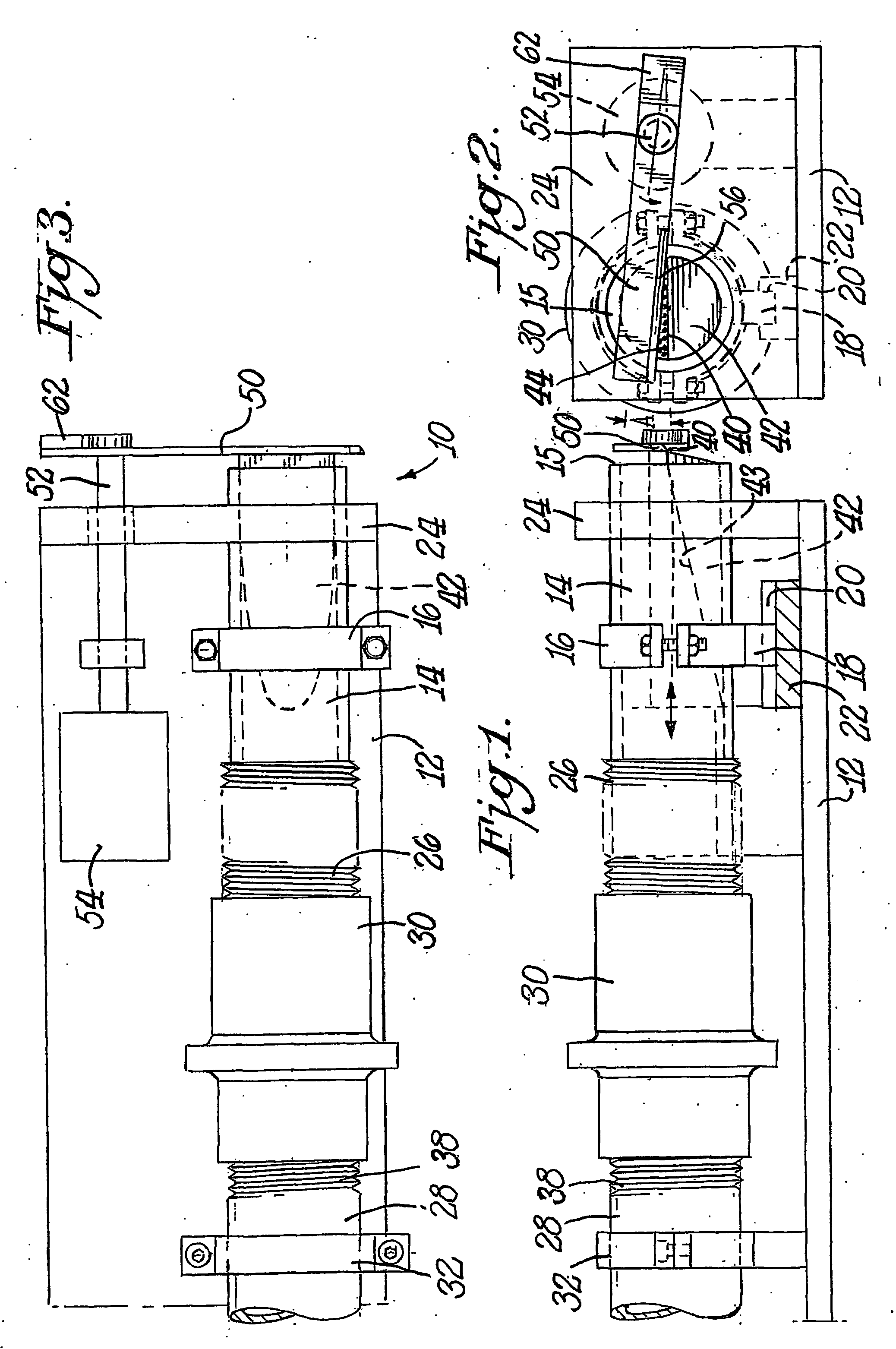
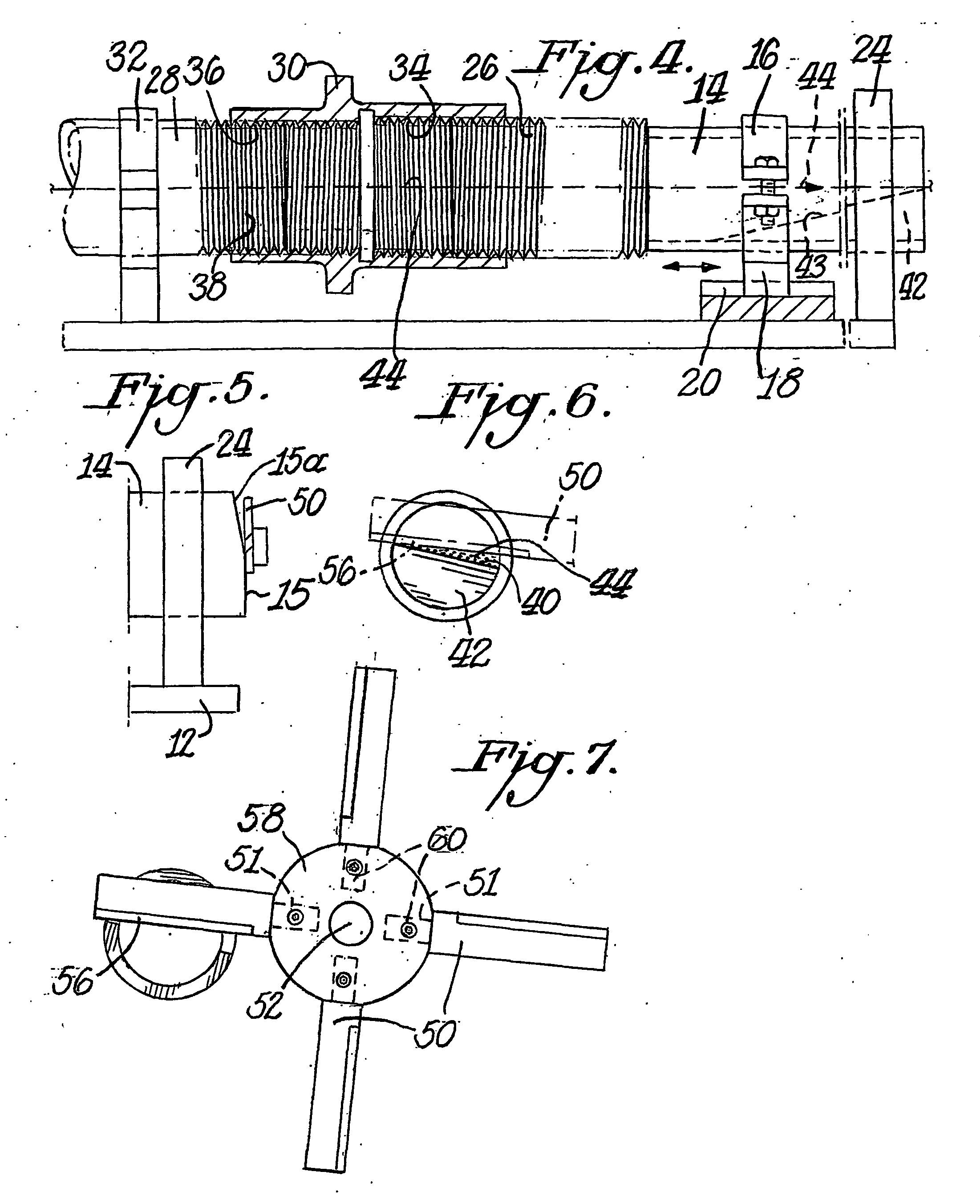
[0027] Some elements of one presently preferred embodiment of the apparatus 10 of this invention are illustrated in FIGS. 1-3. More particularly, a base 12 forms a foundation for mounting an adjustable tube 14 thereon. A clamp 16 affixed to the outer surface of tube 14 contains a guide pin 18 extending from one or more portions of the clamp 16 to prevent rotation of tube 14. The guide pin 18 is free to move longitudinally in slot 20 in a U-shaped guide 22 mounted on base 12. Thus, while guide pin 18 prevents rotation of tube 14, that pin does allow travel of the tube 14 along the longitudinal axis of the tube as it slides in the slot 20 in U-shaped guide 22.

[0028] A mounting bracket 24 holds tube 14 in position relative to base 12 and the adjacent shaft 52 of cutting apparatus described more fully below. A small clearance between the outside circumference of tube 14 and the inside of a bore in bracket 24 permits longitudinal movement of tube 14 with minimum vibration or chatter as ...


PUM

PropertyMeasurementUnit
Angleaaaaaaaaaa
Angleaaaaaaaaaa
Angleaaaaaaaaaa

Abstract

A cutting apparatus for continuous lengths of filaments bundles, film ribbons, filamentary-type or other material in strip like form is disclosed containing a tube that is readily adjustable in very small increments relative to rotating blades. A housing surrounds the exit end of the tube and rotating blades which is attached to a suction device. The device creates a high velocity flow of air through the tube which aligns the filamentary material for cutting. An insert may be placed in the tube which contains an upper surface or anvil at its outer end. The tube and / or the insert in the tube is adjustable in two dimensions relative to one or more blades rotating in a plane transverse to the axis of the tube. These adjustments which may be made during operation of the cutting process to facilitate a cleaner, uniform cutting of the filamentary material.

Description

BACKGROUND OF THE INVENTION [0001] A. Field of Invention [0002] The dependable and accurate cutting of moving and continuous lengths of filament bundles, film ribbons, filamentary tapes or other materials in strip-like form is a challenging and difficult problem, particularly so when the ribbon thickness or the diameter of the filaments is only a few microns. [0003] Such materials have no appreciable stiffness and must be conveyed and aligned by a moving stream of air, feed rolls or other mechanical means or by air jets, or a combination of these, to the cutting location, where it is cut into discrete lengths, the length being determined by dividing the material transport speed by the number of cuts / minute. Fixing these two parameters when cutting filaments, into staple or flock, or ribbons will result in the desirable, uniform length product. [0004] In scrap recovery or disposal systems, where uniform cut length is of little concern, cutting speed is normally fixed but cut length w...

Claims


Application Information

Patent Timeline
IPC IPC(8): B23D19/00B26D1/28B26D7/18D01G1/04
CPCB26D1/28B26D7/1863D01G1/04Y10S83/913Y10S83/95Y10T83/04Y10T83/0524Y10T83/6472Y10T83/768
Inventor BILLINGSLEY, JOHN G.S.
Owner BILLINGSLEY JOHN G S
Why Eureka
Try Eureka