Flash memory controller utilizing multiple voltages and a method of use

a flash memory controller and multiple voltage technology, applied in the field of flash memory controllers, to achieve the effect of simplifying the pin-out of the power source interface of the flash memory controller and improving power consumption efficiency

Active Publication Date: 2006-09-14
KINGSTON DIGITAL CO LTD
View PDF7 Cites 25 Cited by
  • Summary
  • Abstract
  • Description
  • Claims
  • Application Information

AI Technical Summary

Benefits of technology

[0031] A multiple voltage Flash memory controller in accordance with the present invention provides the following advantages over conventional Flash memory controllers: (1) a voltage host is allowed to interface with multiple Flash memory components that operate at different voltages in any combination through the use of a programmable voltage regulator and a voltage comparator; (2) power consumption efficiency is improved by integrating the programmable voltage regulator and voltage comparator mechanism with the Flash memory controller; (3) External jumper selection is eliminated for power source configuration through the above-identified integration; and (4) Flash memory controller power source interface pin-outs are simplified by eliminating redundant power source interface pin outs.

Problems solved by technology

Dual voltage power sources provide a challenge for an intelligent Flash memory controller.

Method used


Image

  • Flash memory controller utilizing multiple voltages and a method of use
  • Flash memory controller utilizing multiple voltages and a method of use
  • Flash memory controller utilizing multiple voltages and a method of use

Examples


first embodiment

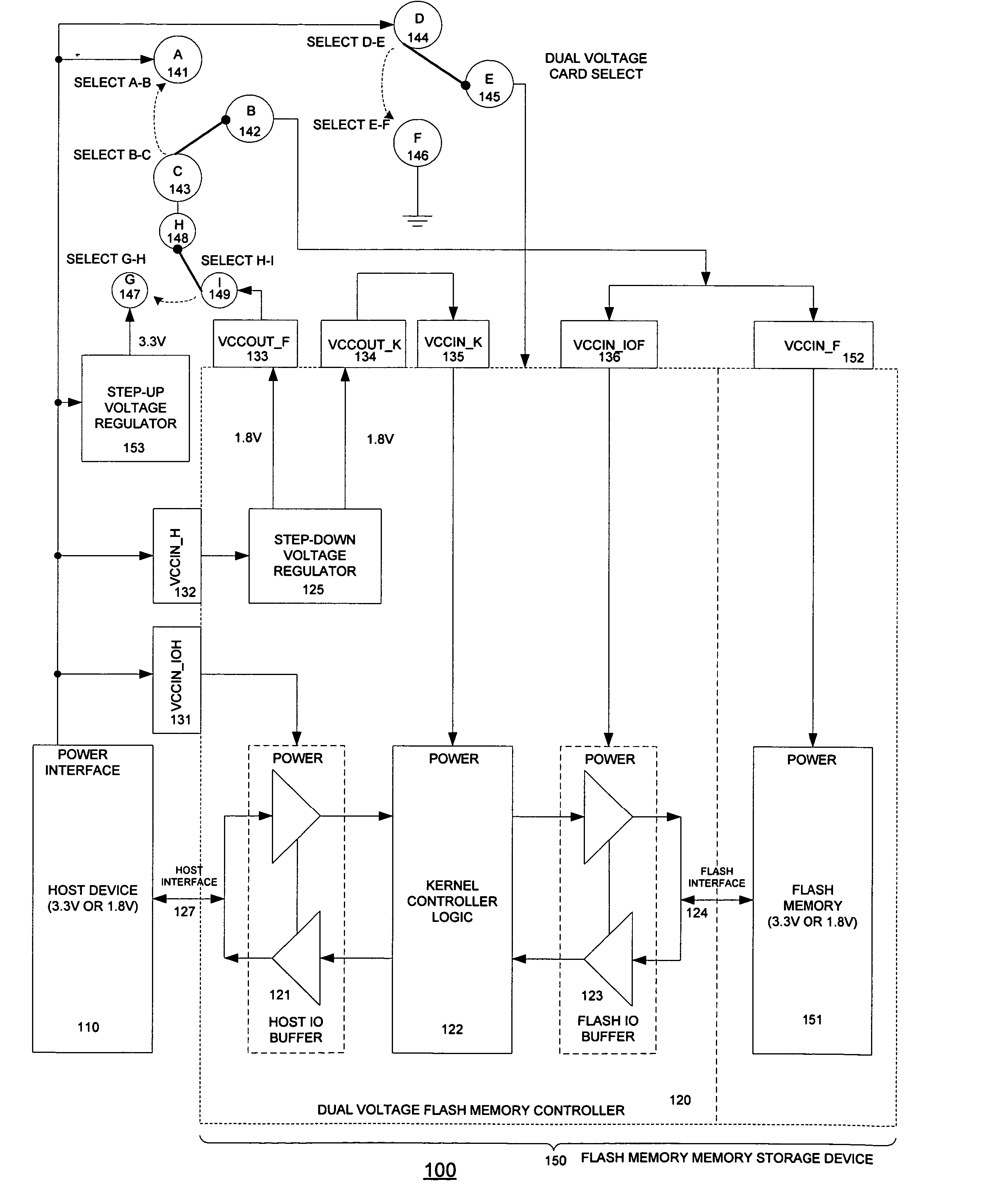
[0047]FIG. 3 is a block diagram of a dual voltage Flash memory controller system in accordance with the present invention. The system 100 comprises a host interface 127, a dual voltage Flash memory controller 120, a step-up voltage regulator 153 and three sets of jumper settings (A, B, C), (D, E, F) and (G, H ,I). In addition, it interfaces with a Flash memory component 151, and a Flash interface 124.

[0048] By adding a separate step-up voltage regulator 153 and a set of jumper settings (G 147, H 148, and I 149) in FIG. 3, the interface combination (b), i.e., in Table 1, Table 2 and Table 3 is supported. It therefore achieves the objective of (a) allowing a high, low or dual voltage host to interface with a high or dual voltage Flash memory component in any combination.

[0049] When the Flash memory card is first manufactured, Flash memory type is determined as either 3.3V or dual voltage. But the host device type can not be known until the Flash memory card is actually plugged into t...

second embodiment

[0056]FIG. 5 is a block diagram of a Flash memory controller system in accordance with the present invention. In this embodiment a voltage comparator 126 and programmable voltage regulator 125 are integrated into dual voltage Flash memory controller 120. In so doing the Flash memory controller system is a standalone system.

[0057]FIG. 6 is a flow chart showing how the intelligent dual voltage Flash memory controller 120 in the invention responds to a query from host device 110 after-power on according to invention FIG. 5. After power-on 500, Flash memory controller 120 detects host voltage 501 through voltage comparator 126. It then sets the proper power switches and tests Flash memory.

[0058]FIG. 7 is a flow chart for setting proper power switches and testing Flash memory accordingly. It first assumes that Flash memory is capable of operating at 1.8 volts 600. It checks the voltage comparator if host device 110 is supplying voltage at 3.3 volt 601? If so, SELECT B-C, SELECT D-E and ...

third embodiment

[0065]FIG. 8 is a block diagram of a Flash memory controller system in accordance with the present invention. In this embodiment FIG. 8 has only one input power source pad VCCIN_IOH 231 and one output power source pad VCCOUT_F 233 is needed and therefore the power source interface pin-outs are simplified. It achieves the objective (d) of simplifying Flash memory controller power source interface pin-outs.

[0066] A multiple voltage Flash memory controller in accordance with the present invention provides the following advantages over conventional Flash memory controllers: (1) a voltage host is allowed to interface with multiple Flash memory components that operate at different voltages in any combination through the use of a programmable voltage regulator and a voltage comparator; (2) power consumption efficiency is improved by integrating the programmable voltage regulator and voltage comparator mechanism with the Flash memory controller; (3) external jumper selection is eliminated f...


PUM


Abstract

A Flash memory controller is disclosed. The Flash memory controller comprises a host interface, a Flash memory interface, controller logic coupled between the host interface, the controller logic handling a plurality of voltages. The controller also includes a mechanism for allowing a multiple voltage host to interface with a high voltage or a multiple voltage Flash memory. A multiple voltage Flash memory controller in accordance with the present invention provides the following advantages over conventional Flash memory controllers: (1) a voltage host is allowed to interface with multiple Flash memory components that operate at different voltages in any combination; (2) power consumption efficiency is improved by integrating the programmable voltage regulator, and voltage comparator mechanism with the Flash memory controller; (3) External jumper selection is eliminated for power source configuration; and (4) Flash memory controller power source interface pin-outs are simplified.

Description

FIELD OF THE INVENTION [0001] The present invention relates generally to Flash memory controllers and more specifically to a Flash memory controller that utilizes multiple voltages. BACKGROUND OF THE INVENTION [0002] A traditional Flash memory storage device, such as an SD card, MMC, USB, Compact Flash (CF) or Memory Stick (MS), operates at a fixed voltage level of 3.3 volts. As mobile communication host devices, such as PDAs and cell phones, proliferate in the market place, a voltage level of power supply to 1.8 volts is needed in order to conserve battery power dissipation. Dual voltage power sources provide a challenge for an intelligent Flash memory controller. The role of the Flash memory controllers is to provide a seamless interface between any combination of host devices, PCs, PDAs or cell phones, and the Flash memory components residing inside Flash memory storage devices. [0003]FIG. 1 is a block diagram of a conventional Flash memory storage device 50, that consists of a h...

Claims


Application Information

Patent Timeline
Patent Type & Authority Applications(United States)
IPC IPC(8): G11C16/04
CPCG11C16/20G11C16/30
Inventor CHEN, BEN WEICHEN, DAVID HONG-DIENSUN, DAVID
Owner KINGSTON DIGITAL CO LTD
Why Eureka
Try Eureka