Apparatus and method for treating female urinary incontinence

a technology for urinary incontinence and abdominal wall, applied in the field of abdominal wall and abdominal wall, can solve the problems of high vascular injury rate, disadvantageous requirement for needles to exit the lower abdominal wall, comparatively large needles used for inserting tapes, etc., to reduce the likelihood of inflammation, minimize the likelihood of urethra adhesion, and minimize the likelihood of urethra abrasion and the effect of reducing the likelihood of infection

Inactive Publication Date: 2006-09-14
COLOPLAST AS
View PDF103 Cites 174 Cited by
  • Summary
  • Abstract
  • Description
  • Claims
  • Application Information

AI Technical Summary

Benefits of technology

[0035] It is preferable if the implant has minimal mass to reduce the likelihood of inflammation or rejection of the implant when it is located in the body. Further, it is preferable that the implant comprises as little material as allows support of the urethra during periods of increased intra-abdominal pressure to minimize the abrasion or the urethra and the likelihood of adhesions forming at the urethra.
[0036] In addition, it is advantageous if the tissue anchors and the suburethral support are integral with each other as it allows easier manufacture of the implant. As the distance from the supporting region under the urethra to the fixing points in the fibro-fat...

Problems solved by technology

Whilst highly effective in treating urinary incontinence, this procedure has a number of problems.
One such problem is that the needles used for inserting the tape are comparatively large, with the needles having, for example, a diameter of around 5-6 mm and a length of around 200 mm.
As well as causing concern for patients viewing such needles before or during the procedure (which is carried out under local anesthetic), this can also lead to a high vascular injury rate.
Similarly, the requirement that the needles exit the lower abdominal wall is disadvantageous due to the trauma to the patient in this area and pain of such abdominal wounds.
A further disadvantage is that the tape comprises a relatively large foreign body mass to be retained within the patient ...

Method used


Image

  • Apparatus and method for treating female urinary incontinence
  • Apparatus and method for treating female urinary incontinence
  • Apparatus and method for treating female urinary incontinence

Examples


Embodiment Construction

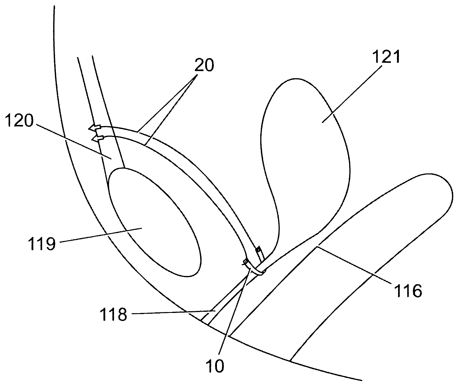
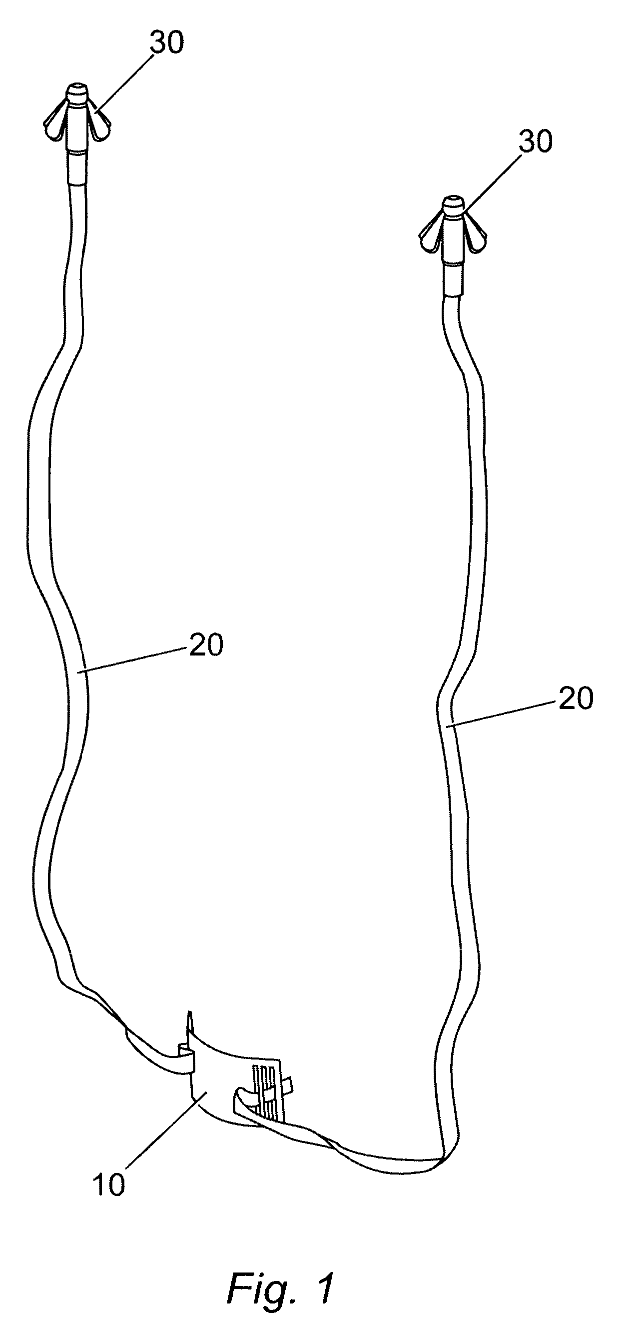
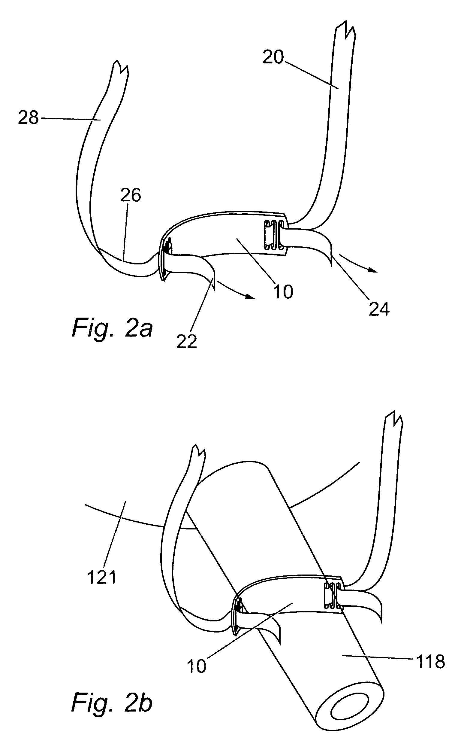
[0186] Referring to FIG. 1, a surgical implant for treating female urinary incontinence has a suburethral support 10, suspending means 20 and at least two soft tissue anchors 30, the suburethral support 10 being positioned in use, loosely under the urethra. The suburethral support has a length L of around 25 mm and a width W of around 10 mm such that it passes around the urethra with a minimum of excess material, although other similar dimensions would also be suitable. In this example, the suburethral support 10 is made from flat polymer tape. At each side 11,13 of the suburethral support 10 suspending means 20 are provided which attach to the suburethral support 10 at a first end 22,24.

[0187] The suspending means 20 are attached at a second end 26 to a respective soft tissue anchor 30.

[0188] As shown in FIGS. 7a-7C, the soft tissue anchor 30 of the embodiment described comprises a central portion 32 and four winged sections 34 which are attached to the central portion at a first...


PUM

PropertyMeasurementUnit
Lengthaaaaaaaaaa
Mechanical propertiesaaaaaaaaaa
Biocompatibilityaaaaaaaaaa

Abstract

The present invention provides a surgical implant and method for supporting the urethra where the implant includes a suburethral support suspended between two soft tissue anchors. The surgical implant is introduced into at least one incision made on the upper wall of a vagina with the first soft tissue anchor inserted on a first side of the urethra behind the pubic bone, and the second soft tissue anchor inserted on a second side of the urethra behind the pubic bone, such that the suburethral support is suspended from the soft tissue anchors and supports the urethra. Each of the first and second soft tissue anchors are inserted in, and fix in, the soft tissue of the perineum without penetrating the obturator foramen.

Description

RELATED APPLICATIONS [0001] This application is a continuation-in-part of co-pending U.S. patent application Ser. No. 10 / 510,488 filed Mar. 28, 2005, entitled “Apparatus And Method For Treating Female Urinary Incontinence,” and a continuation-in-part of co-pending U.S. patent application Ser. No. 11 / 199,061, filed Aug. 8, 2005, entitled “Apparatus And Method For Treating Female Urinary Incontinence,” which is a continuation of U.S. patent application Ser. No. 10 / 398,992, filed Apr. 11, 2003, entitled “Apparatus And Method For Treating Female Urinary Incontinence,” and which issued as U.S. Pat. No. 6,960,160 on Nov. 1, 2005, the entire contents of each of which are incorporated herein in their entireties.FIELD OF THE INVENTION [0002] This invention relates to an apparatus and method for treating female urinary incontinence and, in particular, to a surgical implant having a sling that passes under the urethra in use and supports the urethra to alleviate incontinence, along with relate...

Claims


Application Information

Patent Timeline
IPC IPC(8): A61F2/00
CPCA61B17/00491Y10T29/49826A61B17/0469A61B17/06066A61B17/06109A61B19/54A61B2017/00805A61B2017/0409A61B2017/0412A61B2017/0417A61B2017/0427A61B2017/0464A61F2/0045A61F2220/0016A61F2250/0031A61F2250/0051A61F2/0063A61B17/0401A61B17/3468A61B90/39A61F2002/0072
Inventor BROWNING, JAMES
Owner COLOPLAST AS
Why Eureka
Try Eureka