

Bandage with splint
a bandage and splint technology, applied in the field of medical devices, can solve the problems of reducing sanitation, difficult to apply bandages to and retain bandages on many parts of the body, and difficulty in bandage retention by fingers, so as to promote healing, facilitate and facilitate use, and easy and economical manufacturing
- Summary
- Abstract
- Description
- Claims
- Application Information
AI Technical Summary
Benefits of technology
Problems solved by technology
Method used
Image

Examples
first embodiment
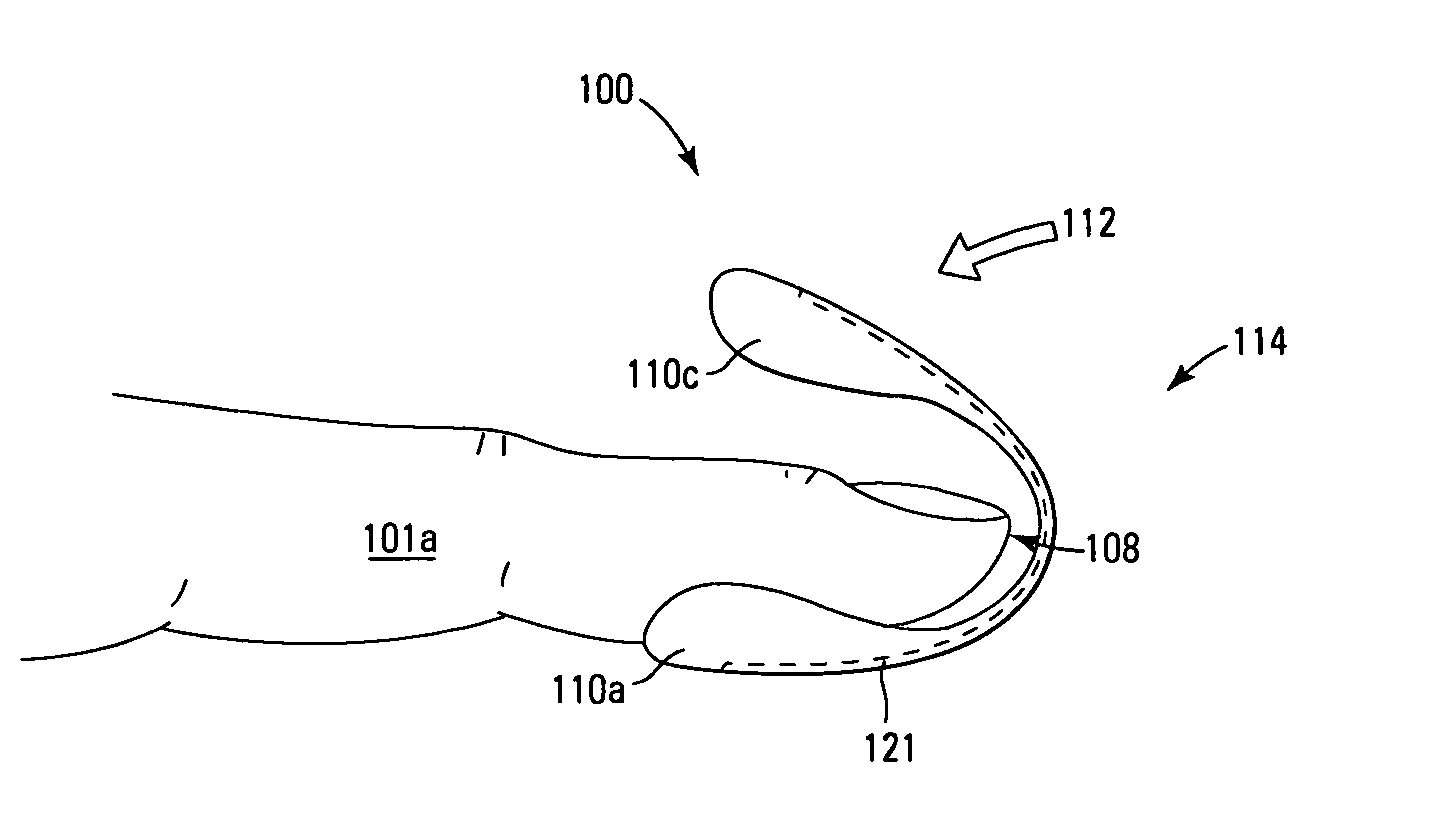
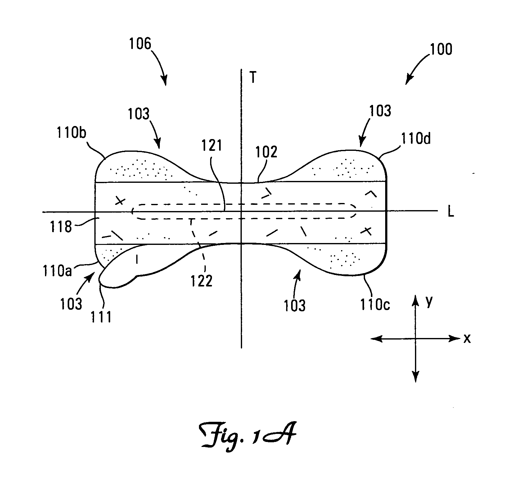
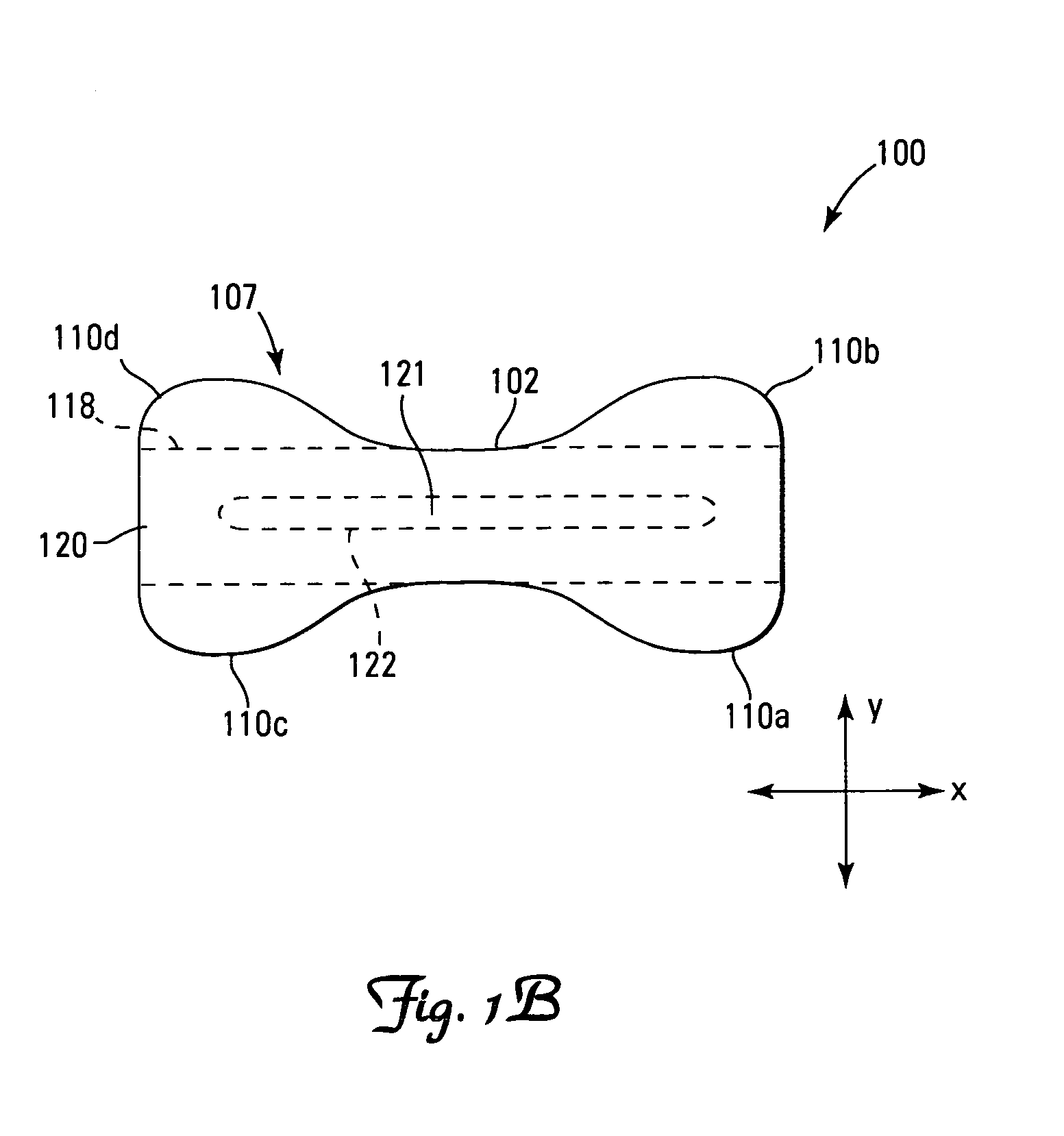
[0133] The bandage 100 shown in FIGS. 1A to 1G can be oriented with a longitudinal centerline L generally bisecting the bandage 100. The term “longitudinal” refers to a line, axis, or direction in the plane of the bandage 100 that is aligned with an “x” axis. The bandage 100 shown in FIG. 1A can further be oriented with a transverse (or lateral) centerline T that refers to a line, axis, or direction aligned with a “y” axis that is perpendicular to the longitudinal “x” axis. The bandage 100 can further be oriented with an axis in the “z” direction, which is perpendicular to the x-y plane (defined by the longitudinal and transverse centerlines), and generally corresponds to the direction associated with the thickness dimension of the bandage 100. The shape of the bandage 100 is defined by its peripheral edge 102.
[0134] The length of the bandage 100 is the maximum dimension measured parallel to the longitudinal centerline L in the longitudinal direction. The width of the bandage 100 i...
second embodiment
[0160]FIG. 2A shows a bandage 200 according to the second embodiment. The bandage 200 can substantially resemble the one shown in relation to FIGS. 1A to 1G, with at least one difference. The bandage 200 shown in FIG. 2A can have a splint 221 attached to the exterior side 207 of the exterior layer 220 of the bandage 200. The splint 221can be attached, for example, with adhesive.
[0161] As with the first embodiment of the bandage 100, the second embodiment of the bandage 200 can be applied to the index finger 201a. First the release liner (not shown) can be removed from the tabs (only tabs 210a and 210c shown) and the tabs located at one end of the bandage 200 (only tab 210a shown) can be applied to the finger 201a. At this stage of application, the bandage 200 can remain relatively straight in a longitudinal direction because of the splint 221. Next, the bandage 200 can be bent around the distal end 208 of the finger 201a. Finally, the tabs located at the other end of the bandage 20...
third embodiment
[0162]FIG. 3A shows the exterior side 307 of a bandage 300 according to the third embodiment. The bandage 300 can substantially resemble the one shown in relation to FIGS. 1A to 1G, with certain differences. The shape of the bandage 300 is defined by its peripheral edge 302 and defines an interior side (not shown) and an exterior side 307. Fastening tabs 310a, 310b, 310c and 310d can be formed as lateral extensions of the exterior layer 320 beyond the edge of the interior layer 318. The bandage 300 shown in FIG. 3A can have a splint 321 that is shaped by the peripheral edge 322 differently from the shape of the splint 121 shown in relation to FIGS. 1A to 1G. Moreover, the splint 321 can be mounted on the exterior layer 320 similar to the splint 221 shown in relation to FIG. 2A. The exterior layer 320 could be made of a clear or opaque material. Such a material could be a transparent perforated ethylene vinyl acetate tape coated on one side with an acrylate adhesive. Such a tape is o...
PUM
 Abstract
Description
Claims
Application Information