Piston and method of manufacture

a manufacturing method and piston technology, applied in the direction of trunk pistons, machines/engines, plungers, etc., can solve the problems of difficult to produce substantially uniform sidewall thickness, difficult to produce gallery shapes and sidewall thickness using conventional machining of forged or cast part blanks, etc., to achieve uniform bowl, low cost, and simple

Inactive Publication Date: 2006-09-21
FEDERAL MOGUL WORLD WIDE
View PDF8 Cites 66 Cited by
  • Summary
  • Abstract
  • Description
  • Claims
  • Application Information

AI Technical Summary

Benefits of technology

[0015] The invention has the advantage of providing a simple, low-cost method for welding the head and base portions to form a monobloc piston having a closed oil gallery and an eccentric combustion bowl having a substantially uniform bowl sidewall thickness.

Problems solved by technology

It will be appreciated that such an architecture presents a challenge to joining the portions by traditional circumferential induction welding, since access to the inner set of forming surfaces is limited and with respect to the positioning of an induction coil next to the mated joining surfaces.
While this method has been found to be very desirable for joining monobloc pistons, it use has been limited to generally axisymmetric pistons.
This joining method has not been used for such piston designs because according to this method, the respective joining surfaces require a concentric relationship with respect to the longitudinal axis of the piston, while the eccentric placement of the bowl and raised portion thereof with respect to the piston axis makes it difficult to produce a substantially uniform sidewall thickness, particularly when using conventional machining and other material removal methods for forming the first and second parts.
Such gallery shapes and sidewall thickness are difficult to produce using conventional machining of forged or cast part blanks, particularly if narrow sidewall geometry is desired to improve cooling efficiency.
This difficulty of forming the gallery is further exacerbated if the gallery is a closed gallery, because of the need to form portions of the non-axisymmetric gallery in both parts, and further, to join the parts while maintaining their corresponding axial and radial alignment.

Method used


Image

  • Piston and method of manufacture
  • Piston and method of manufacture
  • Piston and method of manufacture

Examples


Embodiment Construction

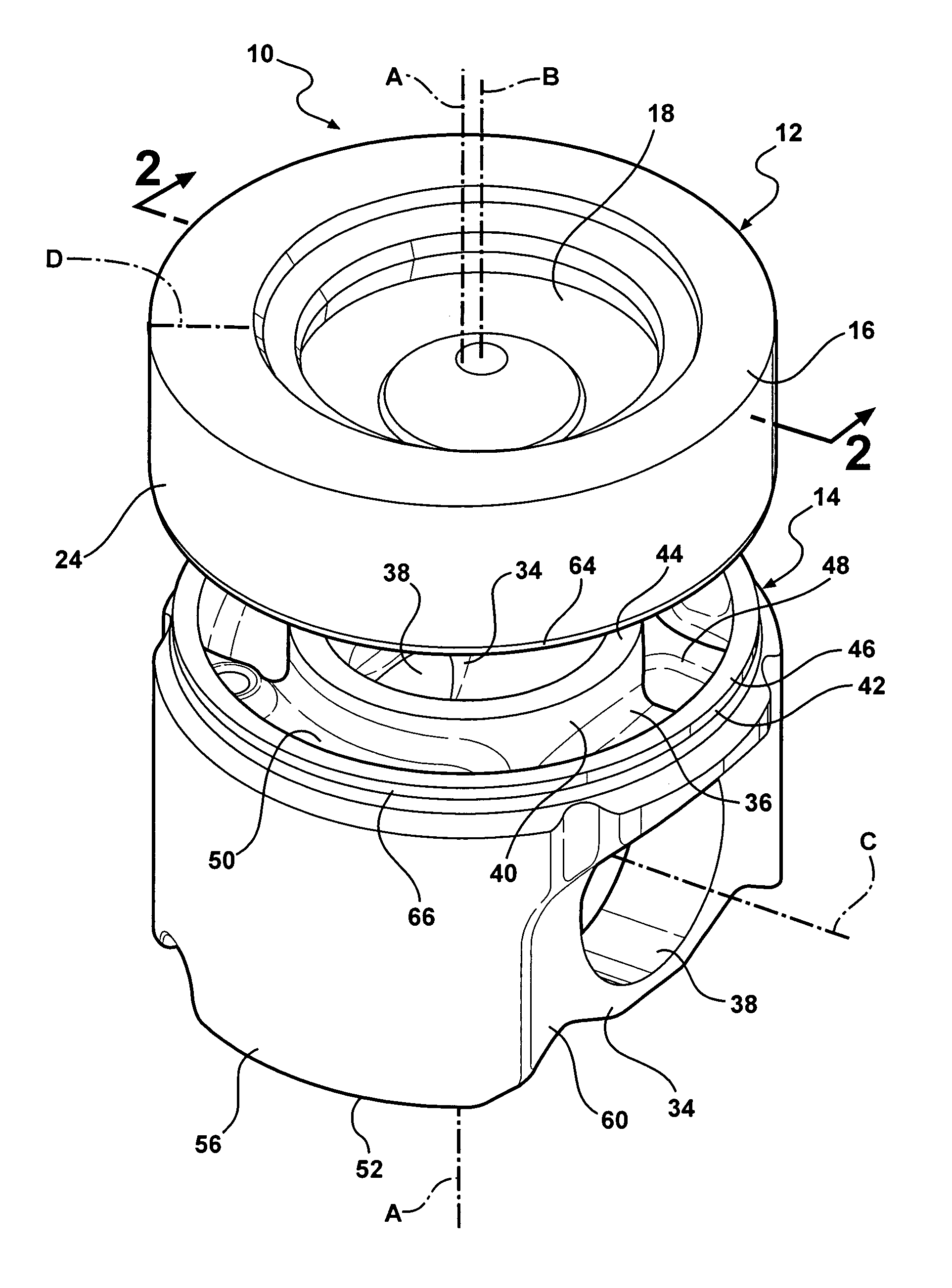
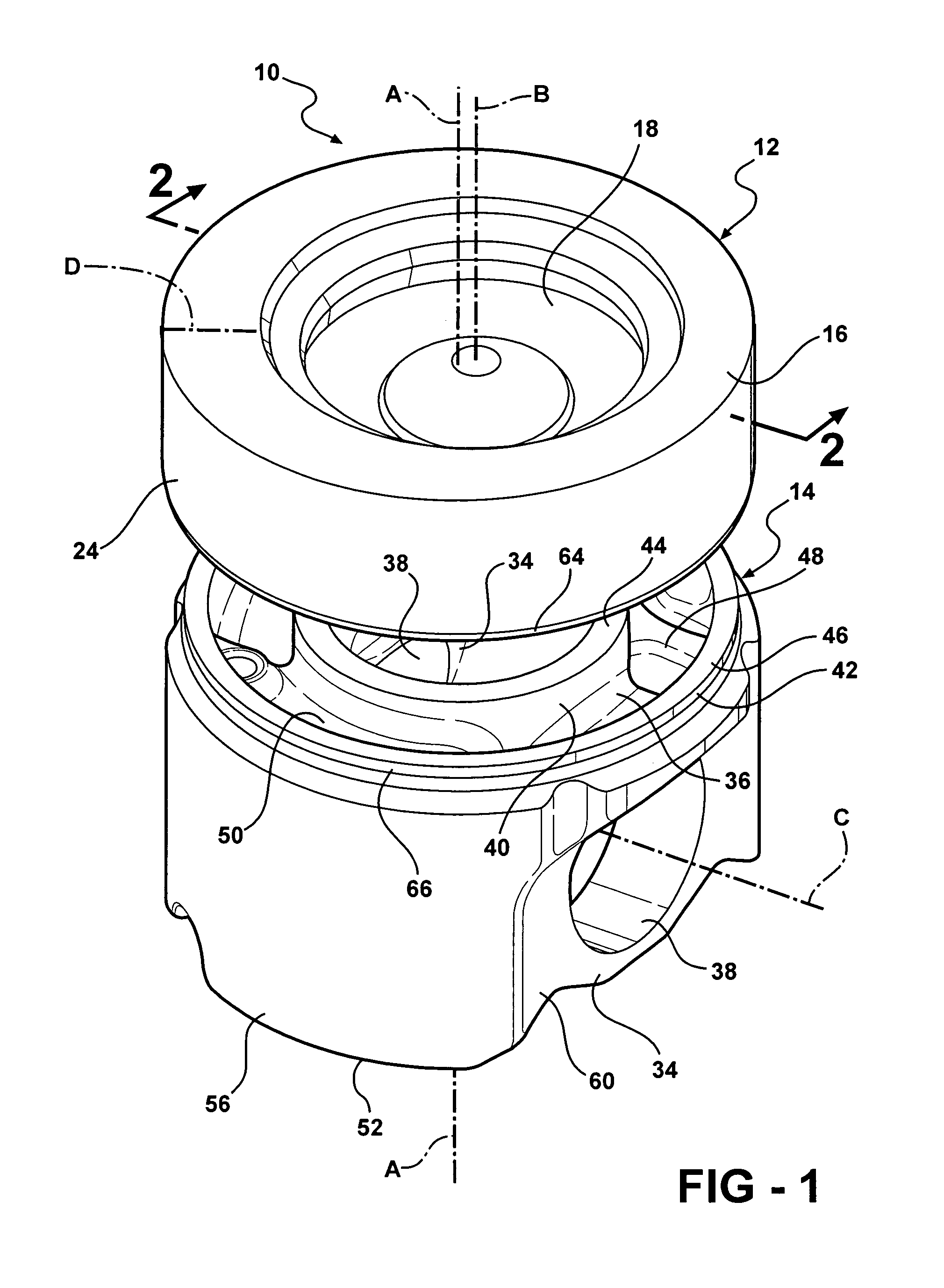
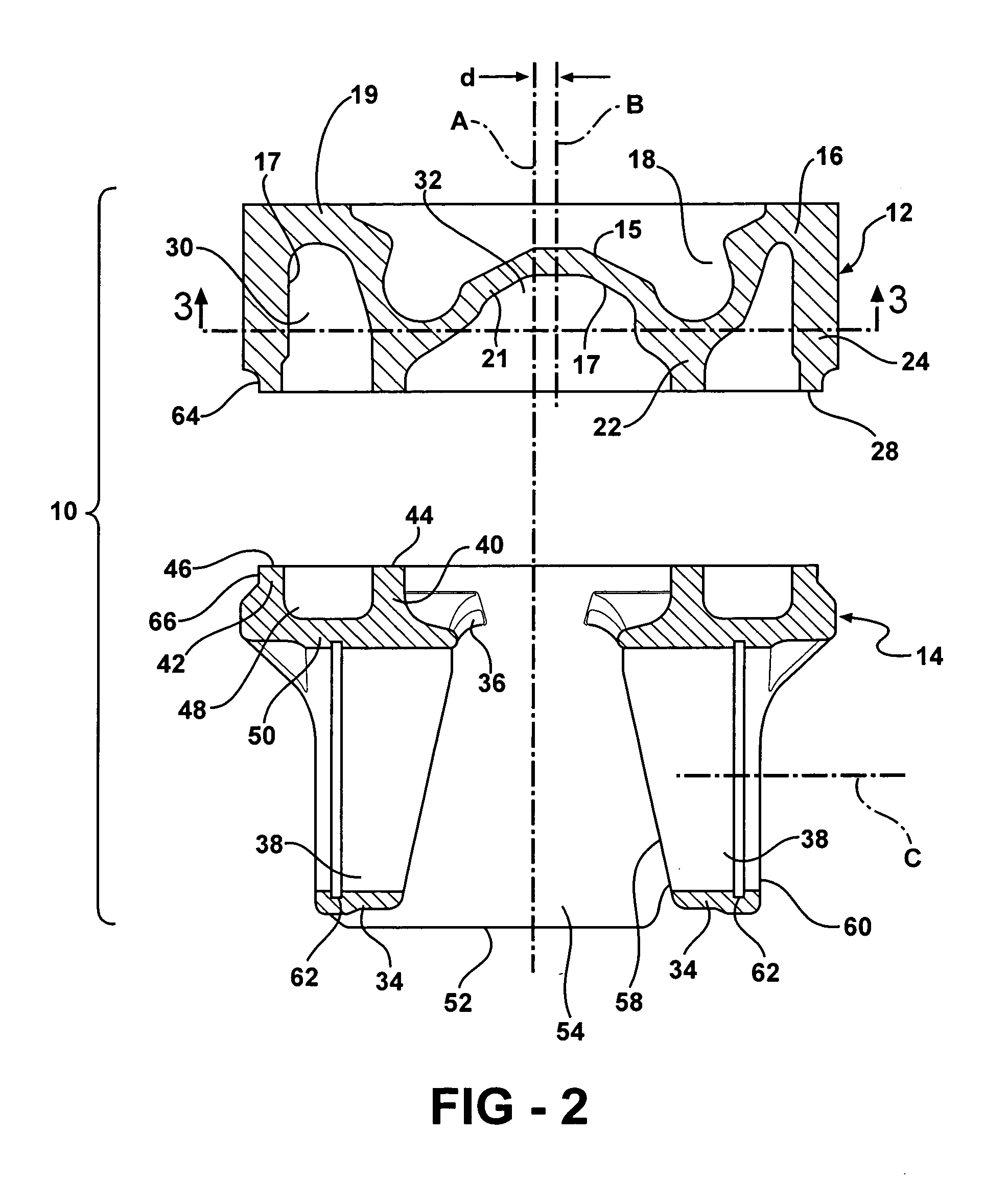
[0025] Referring to FIGS. 1-8, a monobloc piston constructed according to a presently preferred embodiment of the invention is shown generally at 10 in the drawings and is fabricated of at least two parts which are formed separately from one another in a manner to provide at least two sets of circumferentially extending mateable joining surfaces which are initially spaced apart from one another and heated to a temperature sufficient for welding the parts, after which the heating of the surfaces is terminated and the surfaces are joined to one another to affect a permanent weld between the parts.

[0026] Referring to FIGS. 1-7, in the illustrated embodiment, piston 10 includes a head portion 12 and a base portion 14. Both head portion 12 and base portion 14 are fabricated of metal, and are preferably formed from steel alloys, although the invention is not limited to these materials. As will be explained further below, the piston and method are particularly adapted for use with high te...


PUM


Abstract

A piston particularly adapted for heavy-duty diesel engine applications is fabricated from a separate head portion and base portion having circumferentially extending joining surfaces that are heated prior to bonding to an elevated temperature sufficient to enable bonding of the joining surfaces, and thereafter the joining surfaces brought into contact with one another and twisted to attain a permanent metallurgical weld at the interface of the joining surfaces. The head portion has an eccentric combustion bowl and crown. The joined head portion and base portion together form a monobloc piston having a closed gallery which is adapted to receive a cooling fluid, such as oil. The combustion bowl has a substantially uniform bowl sidewall thickness. The piston and method are particularly adopted for use with steel alloys and other high temperature metal alloys.

Description

BACKGROUND OF THE INVENTION [0001] 1. Technical Field [0002] This invention is related generally to pistons and methods of manufacturing pistons. More particularly, it is related to monobloc pistons having an offset or eccentric combustion bowl and a closed cooling gallery, and methods of their manufacture. [0003] 2. Related Art [0004] In heavy-duty piston applications, such as those used in industrial diesel engines, various methods are known for bonding separately formed portions of a piston in order to yield a piston monobloc structure. In a monobloc piston the crown, sidewall including ring grooves and skirt are either formed together or joined together to form a monolithic piston structure. One joining process used to form heavy-duty monobloc pistons is friction welding in which one portion of the piston is rotated at high speed while pressed against the other portion, with the resulting frictional energy generating sufficient heat to metallurgically bond the portions together....

Claims


Application Information

Patent Timeline
Patent Type & Authority Applications(United States)
IPC IPC(8): F16J1/04
CPCF02F3/003
Inventor GAISER, RANDALL R.
Owner FEDERAL MOGUL WORLD WIDE
Why Eureka
Try Eureka