Multi-junction solar cells with an aplanatic imaging system and coupled non-imaging light concentrator

Inactive Publication Date: 2006-09-21
RGT UNIV OF CALIFORNIA
View PDF16 Cites 77 Cited by
  • Summary
  • Abstract
  • Description
  • Claims
  • Application Information

AI Technical Summary

Benefits of technology

[0005] This system with its combination of elements enables employment of the highly efficient multi-junction solar cell such that a very intense solar flux can be input to the solar cell by the non-imaging light concentrator which is coupled to an aplanatic and planar optical subsystem. While multi-junction solar cells are about 100 times more expensive than conventional cells on an area basic, the system described herein can prov

Problems solved by technology

Solar cells for electrical energy production are very well known but have limited utility due to the very high Kwh cost of production.
While s

Method used


Image

  • Multi-junction solar cells with an aplanatic imaging system and coupled non-imaging light concentrator
  • Multi-junction solar cells with an aplanatic imaging system and coupled non-imaging light concentrator

Examples


example 1

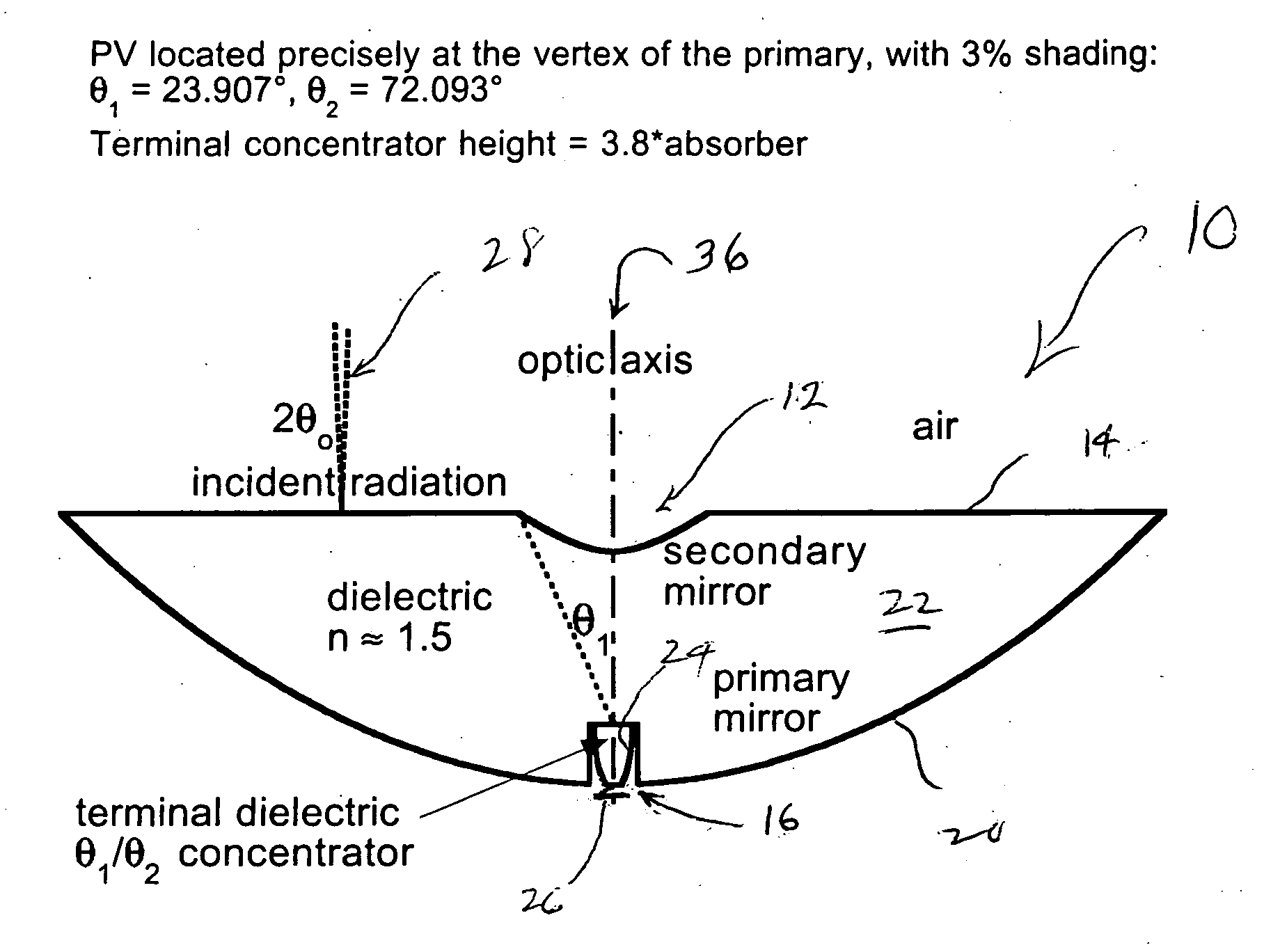
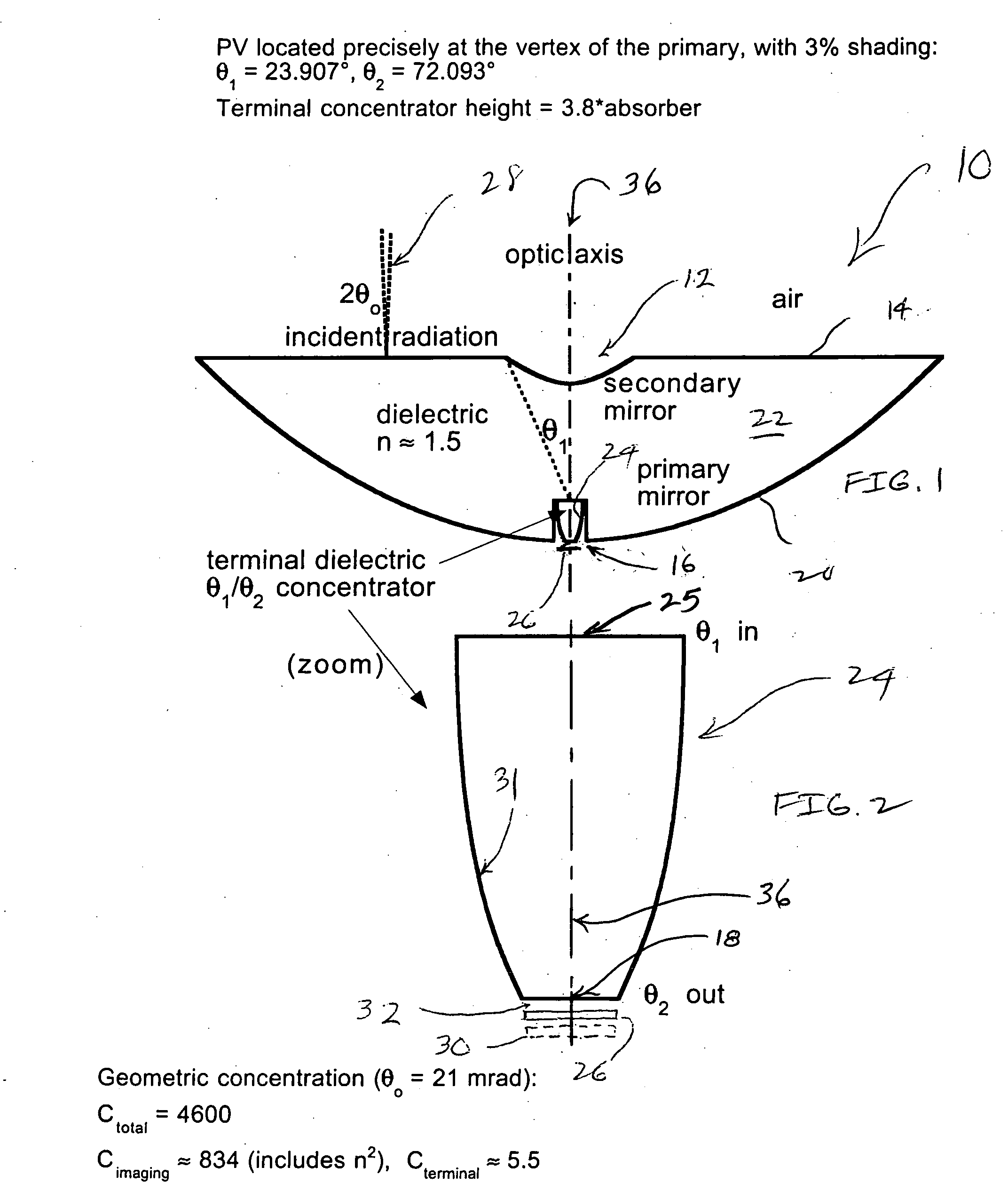
[0023] The optical space is filled with the dielectric 22, i.e., the planar non-imaging concentrator 24 resembles a slab of glass. The multi-junction technology lends itself to small solar cell sizes. This size relationship works better since the high current has a shorter distance to travel, mitigating internal resistance effects. Consequently, it is preferable that the cells 26 are in the one to several square mm sizes. The design choice for NA1 has considerable freedom, a trade-off with shading by the secondary mirror 12, but is typically in the range of about 0.3 to 0.4. Taking n≈1.5, a typical value for glasses (and plastics) we have θc≈420. Then from Equation (1), (θ1+θ2)≦960, we take NA1=0.4n, θ1≈23.50 and θ2 can be as large as 720, a perfectly reasonable maximum irradiance angle on the multi-junction solar cell 26. At the same time, NA2≈0.95n, within 5% of the etendue limit.

example 2

[0024] In another embodiment the non-imaging optical concentrator (or illuminator) is a cylinder with θ1=θ2. The angular restrictions imposed depend on the desired conditions. If TIR is desired and the solar cell is optically coupled to the multi-junction solar cell 26 (or the light source 30 for the illuminator), θ1 should not exceed (900−θc) ≈480. If TIR is desired and there is a small air gap between the concentrator and the multi-junction solar cell 26 (or the light source 30 for the illuminator), θ1 should not exceed θc≈420. If the cylinder is silvered and the concentrator is optically coupled to the multi-junction solar cell 26 (or the light source 30 for the illuminator) there is no restriction. If the cylinder is silvered and there is a small air gap between the concentrator and the multi-junction solar cell 26 (or the light source 30 for the illuminator), θ1 should not exceed θc≈420.

example 3

[0025] In another embodiment, radiation is allowed to emerge to accommodate a small air gap between the concentrator and the multi-junction solar cell 26 (or the light source 30 for the illuminator), then θ1 should not exceed θc≈420. Let θ2=390 and θ1=23.50 as before. Then NA2=n sin(390)=0.94, which is within 6% of the etendue limit.


PUM


Abstract

An optical system for a solar energy device to produce electrical energy. The optical system includes an aplanatic optical imaging system, a non-imaging solar concentrator coupled to the aplanatic system and a multi-junction solar cell to receive highly concentrated light from the non-imaging solar concentrator.

Description

BACKGROUND OF THE INVENTION [0001] The present invention is concerned with a multi-junction solar cell employing an optical system which provides extremely high solar flux to produce very efficient electrical output. More particularly, the invention is directed to a solar energy system which combines a non-imaging light concentrator, or flux booster, with an aplanatic primary and secondary mirror subsystem wherein the non-imaging concentrator is efficiently coupled to the mirrors such that imaging conditions are achieved for high intensity light concentration onto a multi-junction solar cell. [0002] Solar cells for electrical energy production are very well known but have limited utility due to the very high Kwh cost of production. While substantial research has been ongoing for many years, the cost per Kwh still is about ten times that of conventional electric power production. In order to even compete with wind power or other alternative energy sources, the efficiency of productio...

Claims


Application Information

Patent Timeline
IPC IPC(8): H01L31/00
CPCH01L31/0547Y02E10/52
Inventor WINSTON, ROLANDGORDON, JEFFREY M.
Owner RGT UNIV OF CALIFORNIA
Why Eureka
Try Eureka