Liquid light pipe with an aplanatic imaging system and coupled non-imaging light concentrator

a technology of imaging system and liquid light pipe, which is applied in the direction of instruments, lighting applications, and using daylight to achieve the effect of high efficiency

Inactive Publication Date: 2008-10-30
WINSTON ROLAND +1
View PDF17 Cites 39 Cited by
  • Summary
  • Abstract
  • Description
  • Claims
  • Application Information

AI Technical Summary

Benefits of technology

[0006]Aplanatic optical imaging designs are combined with a liquid light pipe and optionally a non-imaging optical system for numerical aperture (NA) matching to produce an ultra-compact light concentrator that performs near the etendue limits. In a solar daylighting system the aplanatic optics along with a coupled liquid light pipe and optionally a non-imaging concentrator angle transformer for NA matching produce light output with very high efficiency.
[0009]This system with its combination of elements enables employment of the highly efficient and low cost liquid light pipe such that a very intense solar flux can be conveyed to an interior space. With concentrated solar flux of 300-500 times ambient insolation, the roof penetration required for the same light output is reduced in area by the same factor. The system described herein can provide highly concentrated sunlight to interior spaces with minimal disruption of building envelope. This feature combined with the low cost high efficiency liquid light pipe makes this system very attractive commercially. The optical system therefore provides the light intensity needed to achieve commercial effectiveness for solar day lighting. Moreover, the concentrating daylighting system can be integrated into buildings in an esthetically pleasing and minimally intrusive way. This feature makes the system attractive for retrofitting of existing buildings, which is problematic for prior art daylighting systems. Another benefit of the concentrating daylighting system is that the liquid light pipe can be easily integrated into conventional light fixtures producing daylight illumination without the glare that is a frequent problem of standard daylighting systems. Moreover, augmentation with electric light is desirable because of the variability of daylight. In our system this is easily achievable by adding complementary electric light sources into the same light fixture. This facilitates control of the overall illumination.

Problems solved by technology

This feature makes the system attractive for retrofitting of existing buildings, which is problematic for prior art daylighting systems.

Method used


Image

  • Liquid light pipe with an aplanatic imaging system and coupled non-imaging light concentrator
  • Liquid light pipe with an aplanatic imaging system and coupled non-imaging light concentrator
  • Liquid light pipe with an aplanatic imaging system and coupled non-imaging light concentrator

Examples


example 1

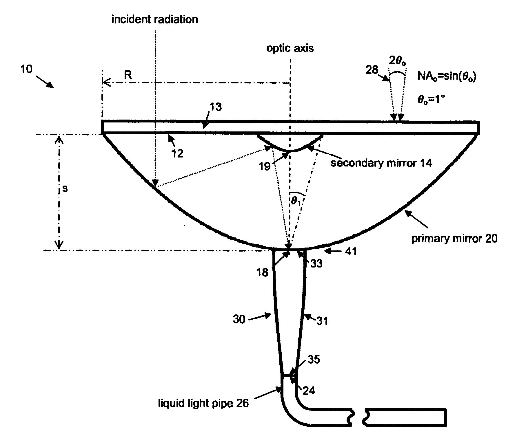
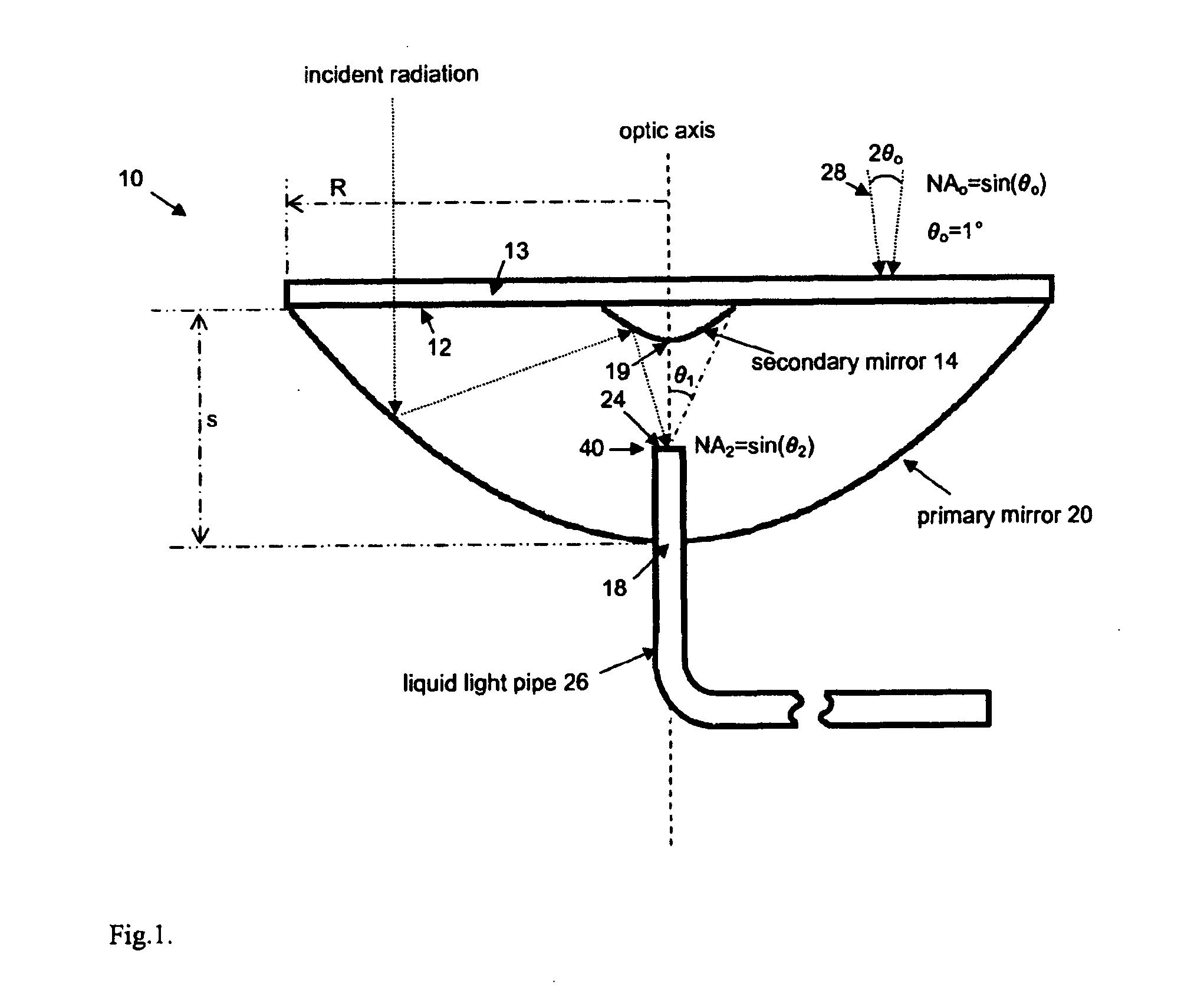
[0025]Primary mirror 20 combined with secondary mirror 14 are elements of an aplanatic design of maximum compactness where 2R / s ≈4, as shown in FIG. 1. The liquid light pipe 26 is positioned with entrance aperture 24 at the focal plane 40 of the two mirror system. The focal plane location 40 is chosen to match the NA of the liquid light pipe, for which 0.42 is a typical value. A transparent cover 13 encases the optics providing protection against the elements. The unit is mounted on a dual axis sun tracker with sufficient angular accuracy to accommodate 28 the angular acceptance (θ0≈1 degree) of the optical system. Notice that sin θ0 ≈NA2 / (C)1 / 2 where C is the geometrical concentration as befitting an etendue limited system.

example 2

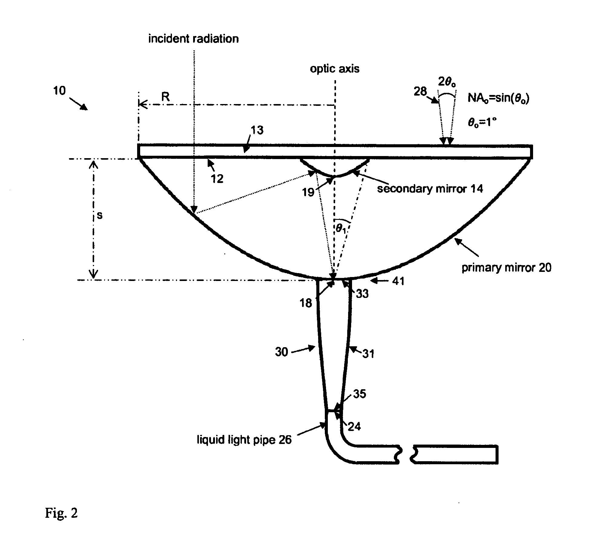
[0026]In another embodiment, which is depicted in FIG. 2, the focal plane of the two mirror system 41 is placed at the vertex 18 of the primary mirror 20 so that the NA1=sin θ1≈0.25. To accommodate the liquid light pipe NA2=0.42 a non-imaging optical concentrator (or angle transformer) 30 is used with θ1=15 degrees, θ2=25 degrees. The nonimaging optical element can operate by total internal reflection.

example 3

[0027]As shown in FIG. 3, the optical system 10, which is mounted on a dual-axis sun tracker 11 that is positioned on the roof of a building 50, concentrates sunlight into the liquid light pipe 26, which conveys the concentrated sunlight through a small roof penetration or an existing duct to a diff-using light fixture 40 that can be mounted on the ceiling or a wall of the room. The concentrated sunlight can be augmented by an electric light source 42 that can be integrated into the diffusing light fixture 40. The light emittance from the diffusing light fixture can be controlled to a constant value with a lighting control system that regulates the light emittance from the electric light source in response to the available sunlight or to the total light output of both the concentrating daylighting and the complementary electric light system.


PUM


Abstract

An optical system for a solar lighting device to provide highly concentrated sunlight to interior spaces with minimal disruption of building envelope. The optical system includes an aplanatic optical imaging system mounted on a dual-axis sun tracker, a non-imaging solar concentrator coupled to the aplanatic system, a liquid light pipe to convey the very intense solar flux to the interior of a building, a diffusing light fixture to spread the daylight into the interior space, and a control system to regulate the light output to a constant and desired level.

Description

[0001]The present invention is concerned with solar daylighting employing an optical system which provides extremely high solar flux to produce very efficient light output. More particularly, the invention is directed to a solar energy system which combines a non-imaging light concentrator, or angle transformer, with an aplanatic primary and secondary mirror subsystem wherein the non-imaging concentrator is efficiently coupled to the mirrors such that imaging conditions are achieved for high intensity light concentration onto a light pipe.BACKGROUND OF THE INVENTION[0002]Daylighting systems are very well known in the form of sky lights which are low cost but can only be used in the top floor of buildings and have the disadvantage of requiring large roof penetrations which lead to undesirable heat loss in winter and heat gain in summer and are prone to rain water infiltration. Daylighting systems employing fiber optics which do not require large roof penetrations and can be used in a...

Claims


Application Information

Patent Timeline
Patent Type & Authority Applications(United States)
IPC IPC(8): F21V8/00F21V33/00
CPCF21S11/00F21S19/005F21V7/0008G02B6/0006G02B6/0008
Inventor WINSTON, ROLANDRITSCHEL, ALEXANDER
Owner WINSTON ROLAND
Why Eureka
Try Eureka