
Automated shade control method and system

a shade control and automatic technology, applied in the field of automatic shade control, can solve the problems of not being able to fully utilize the sensor, no single system currently employs all of these types of systems and controls, and the use of most automated systems is limited to venetian blinds, curtains and other traditional window coverings, etc., to achieve the effect of maintaining a relative brightness of the window area, reducing excessive brightness, and reducing glar

Active Publication Date: 2006-09-21
MECHOSHADE SYST LLC
View PDF34 Cites 207 Cited by
  • Summary
  • Abstract
  • Description
  • Claims
  • Application Information

AI Technical Summary

Benefits of technology

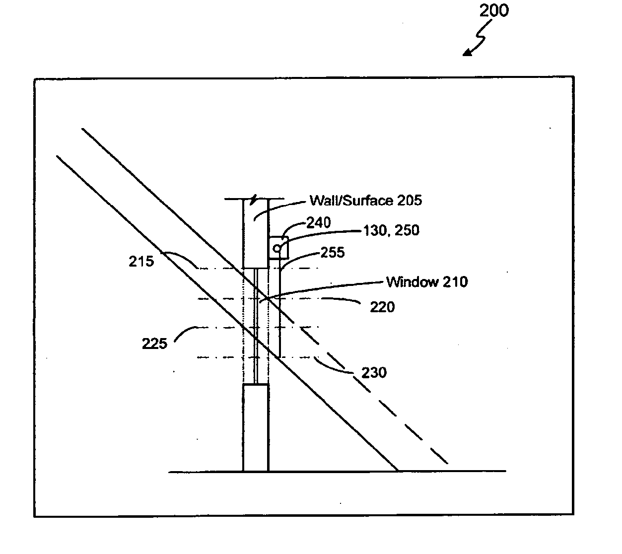
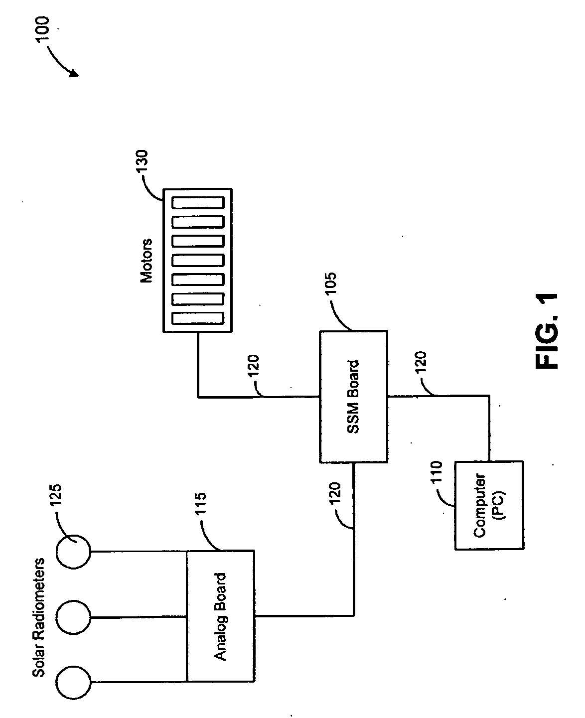
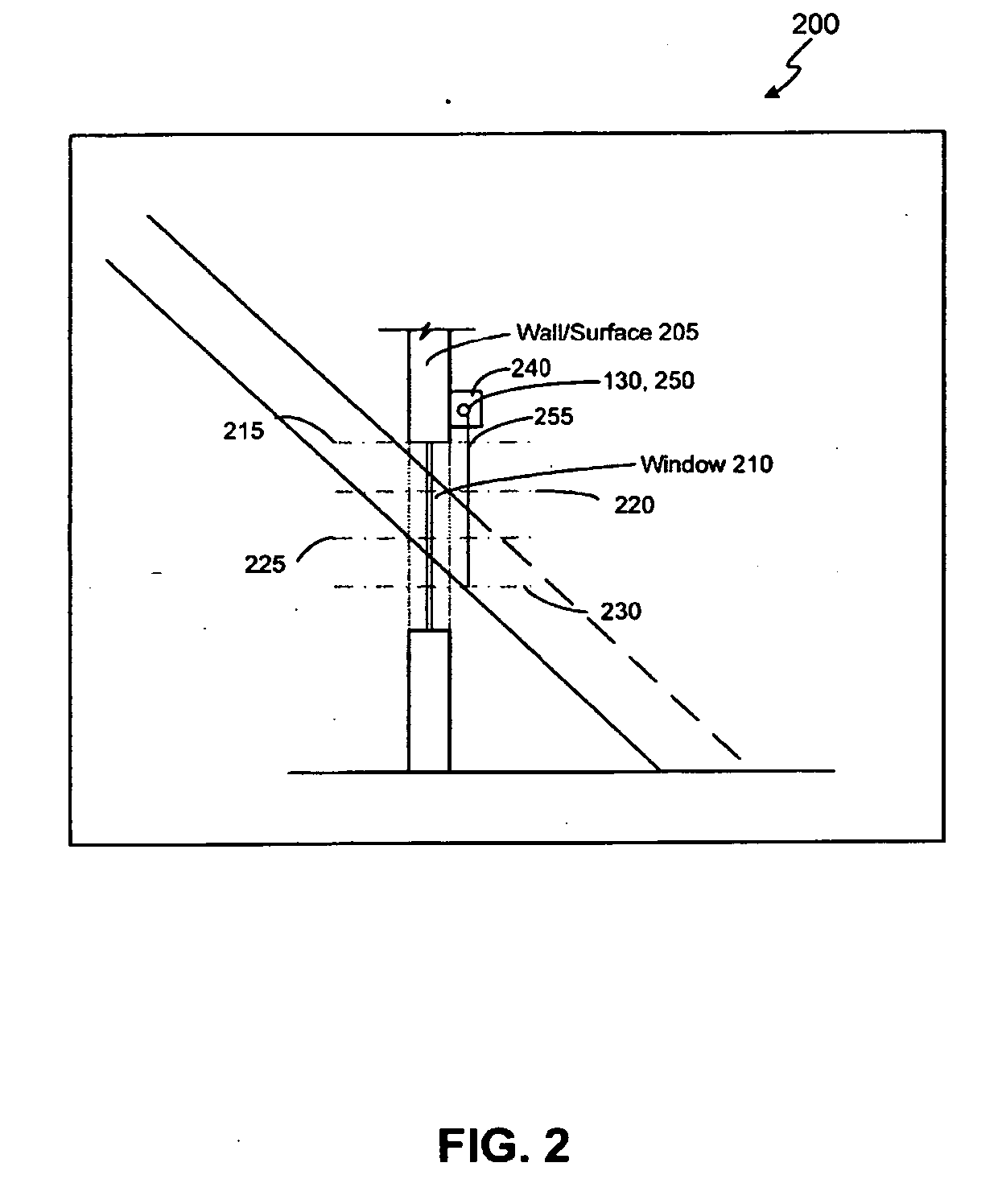
[0009] The automated shade control system of the present invention also includes solar radiometers to measure total solar radiation as well as local area daylight brightness sensors to measure the visible light spectrum. The output of these radiometers and sensors are used in conjunction with automated shade control algorithms to help reduce excessive brightness, veiling glare, and debilitating beamed reflective illumination from bright surfaces from entering the building. This invention further helps maintain a relative brightness of a window area with respect to the brightness of interior surfaces and / or computer screens.

Problems solved by technology

While photo sensors and temperature sensors may be helpful in determining the ideal shading for a window or interior, these sensors may not be entirely effective.
However, no single system currently employs all of these types of systems and controls.
Moreover, most automated systems are designed for, and limited for use with, Venetian blinds, curtains and other traditional window coverings.
Further, prior art systems generally do not utilize information related to the variation of light level within the interior of a structure.
But with the high amount of visible light there is also the bright orb of the sun, excessive heat gain, and debilitating solar rays which will at different times of the year and on different solar orientations penetrate deeply into the building, effecting and impacting on persons working or living therein.

Method used


Image

  • Automated shade control method and system
  • Automated shade control method and system
  • Automated shade control method and system

Examples


Embodiment Construction

[0017] The detailed description of exemplary embodiments of the invention herein shows the exemplary embodiment by way of illustration and its best mode. While these exemplary embodiments are described in sufficient detail to enable those skilled in the art to practice the invention, it should be understood that other embodiments may be realized and that logical and mechanical changes may be made without departing from the spirit and scope of the invention. Thus, the detailed description herein is presented for purposes of illustration only and not of limitation. For example, the steps recited in any of the method or process descriptions may be executed in any order and are not limited to the order presented.

[0018] Moreover, for the sake of brevity, certain sub-components of the individual operating components, conventional data networking, application development and other functional aspects of the systems may not be described in detail herein. Furthermore, the connecting lines sh...


PUM


Abstract

This invention generally relates to automated shade systems that employ one or more algorithms to provide appropriate solar protection from direct solar penetration; reduce solar heat gain; reduce radiant surface temperatures; control penetration of the solar ray, optimize the interior natural daylighting of a structure and optimize the efficiency of interior lighting systems. The invention additionally comprises a motorized window covering, radiometers, and a central control system that uses algorithms to optimize the interior lighting of a structure. These algorithms include information such as: geodesic coordinates of a building; solar position; solar angle solar radiation; solar penetration angles; solar intensity; the measured brightness and veiling glare across a surface; time, solar altitude, solar azimuth, detected sky conditions, ASHRAE sky models, sunrise and sunset times, surface orientations of windows, incidence angles of the sun striking windows, window covering positions, minimum BTU load and solar heat gain.

Description

CROSS-REFERENCE TO RELATED APPLICATIONS [0001] This invention is a continuation-in-part of U.S. application Ser. No. 10 / 906,817 filed on Mar. 8, 2005, and entitled “AUTOMATED SHADE CONTROL METHOD AND SYSTEM.” The '817 application itself claims priority to and the benefit of U.S. Provisional Application No. 60 / 521,497 filed on May 6, 2004, and entitled “AUTOMATED SHADE CONTROL METHOD AND SYSTEM,” the entire contents of both are hereby incorporated by reference.FIELD OF INVENTION [0002] This invention generally relates to automatic shade control, and more specifically, to automated shade systems that employ one or more algorithms to provide appropriate solar protection from direct solar penetration; reduction in solar heat gain; reduction in radiant surface temperatures (of the window wall); controlled penetration of the solar ray, optimization of the interior natural daylighting of a structure and optimization of the efficiency of interior lighting systems. BACKGROUND OF INVENTION [0...

Claims


Application Information

Patent Timeline
IPC IPC(8): E06B9/56
CPCE06B9/32E06B9/322E06B9/56E06B9/68Y02B80/50E06B2009/6827Y02B80/00Y02A30/24E06B9/38G05B11/01
Inventor BERMAN, JOELBERMAN, JANGREENSPAN, ALEXHEBEISEN, STEPHEN
Owner MECHOSHADE SYST LLC
Learn More