
Garnet filtration system for use with water jet cutting tools

a technology of centrifugal filtration and which is applied in the direction of filtration separation, separation processes, manufacturing tools, etc., can solve the problems of frequent down time frequent breakdown and damage of the pump used to draw the particulate slurry through the filtration system, and reduce the use of water jet cutting tools. , the effect of eliminating substantial equipment repair costs and reducing down tim

Inactive Publication Date: 2006-09-21
EBBCO
View PDF8 Cites 10 Cited by
  • Summary
  • Abstract
  • Description
  • Claims
  • Application Information

AI Technical Summary

Benefits of technology

[0010] Thus, the invention advantageously provides for a cost effective efficient system that is resilient to the harsh environment of the abrasive particulate slurry. By removing a seal between the pump shaft and housing a critical point of failure is removed thus eliminating substantial down time and significant equipment repair costs. Instead, the invention advantageously provides a second housing for collection and distribution of fluid that seeps into the second housing. Further, the invention provides significant advantage over the alternative system using an open container to collect fluid that seeped out of the pump housing. Since the invention eliminates the need for this container, there is no need to de-sludge, maintain and provide space for such a container.

Problems solved by technology

Due to the abrasive character of the particulate the water and particulate slurry is abrasive and damaging to the particulate filtration system.
In particular, the pump used to draw the particulate slurry through the filtration system is subject to frequent breakdown and to damage caused by the particulate especially in areas around seals of the pump.
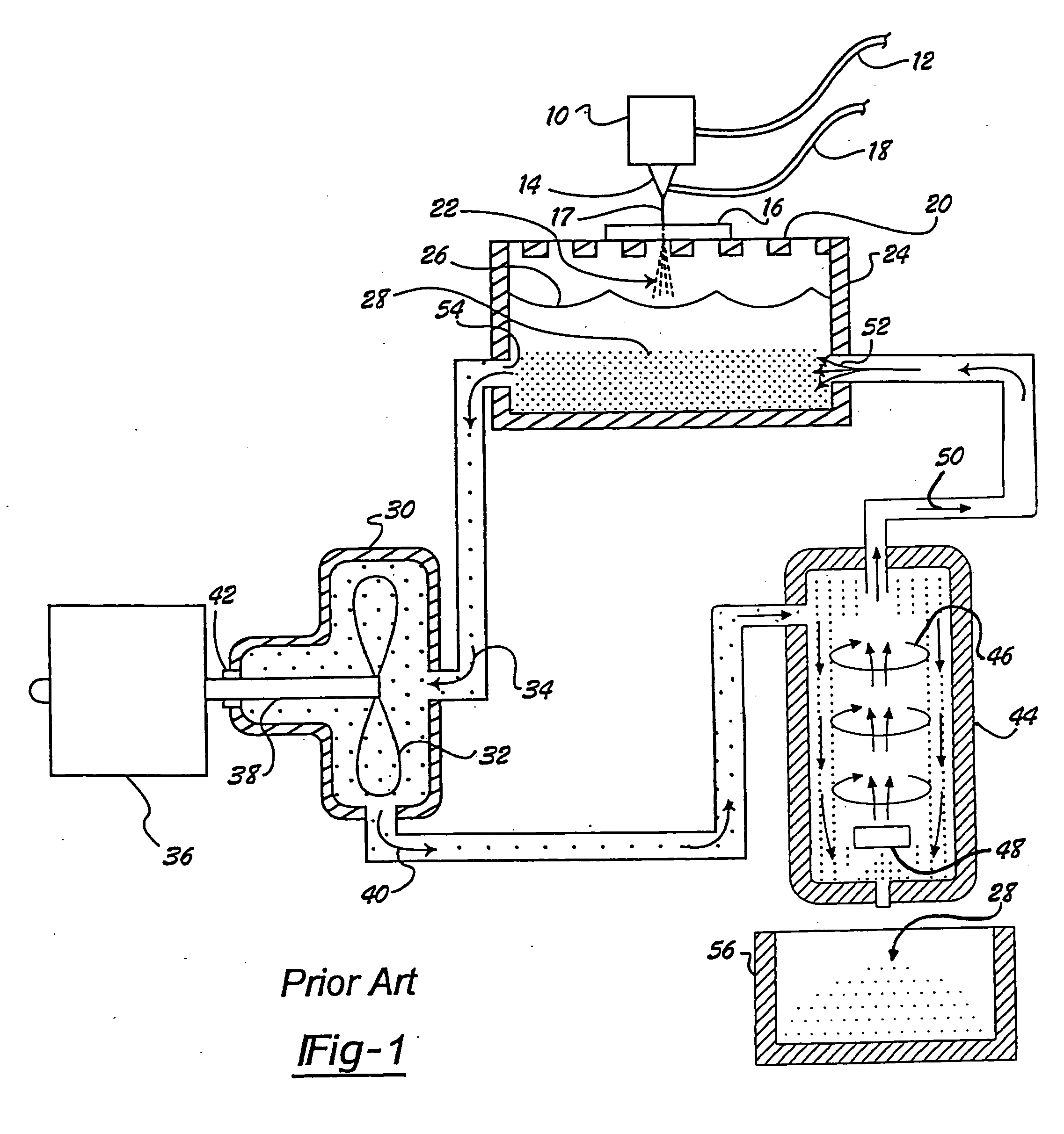
Due to the high and consistent failure rate for the seals 42 around the drive shaft 38 of the pump 30 this prior art system caused frequent down time for the water jet cutting tool since it is required to continually remove the particulate and water slurry that accumulates in the catch tank.
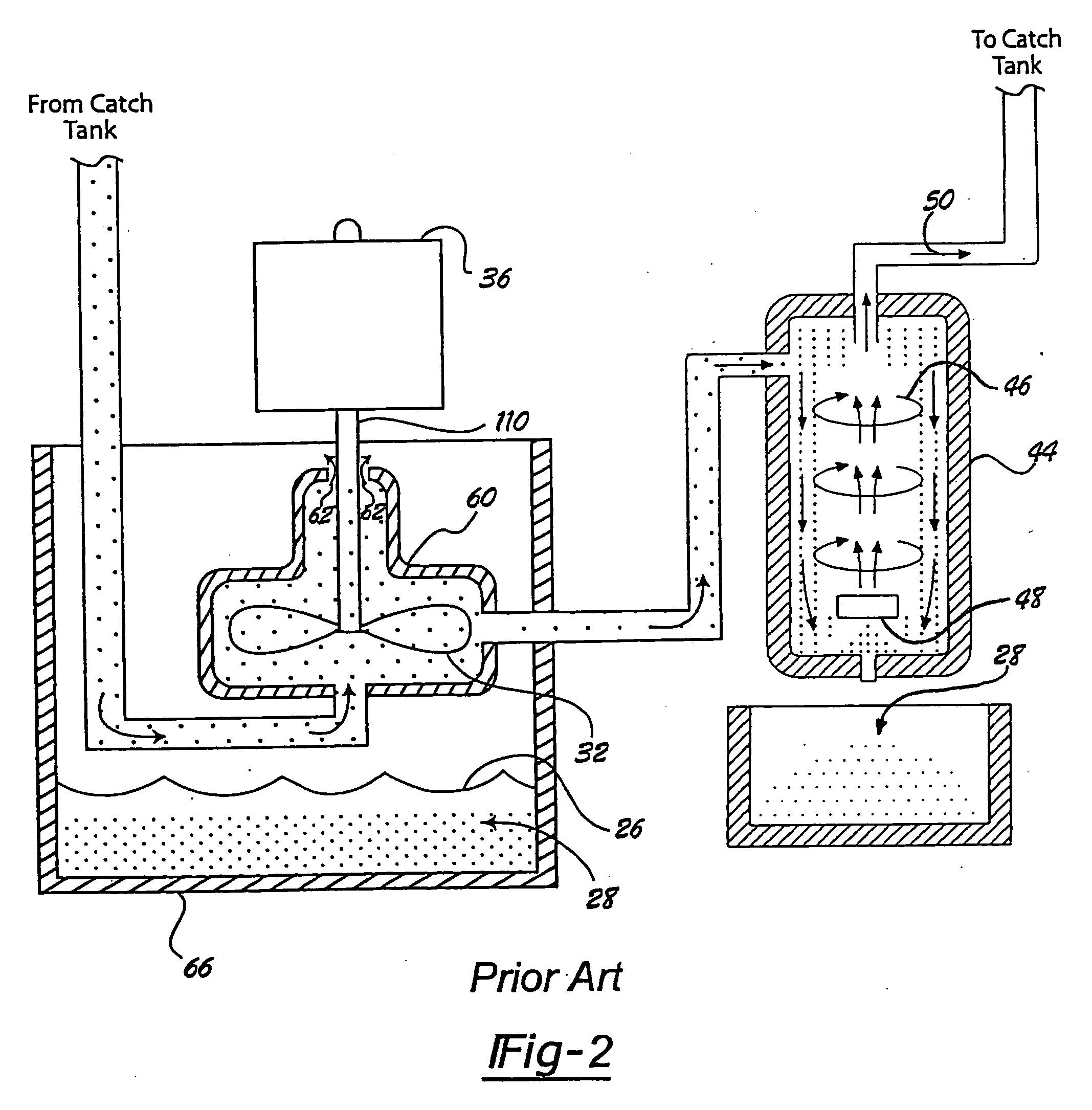
The requirement of a second catch tank 66 made the entire filtration system bulky and added additional cost in providing a second catch tank 66.
This is complicated by the settling of the particulate out of the water at the bottom of the second catch tank 66.
The additional space requirements and maintenance costs of this second prior art system are burdensome.

Method used


Image

  • Garnet filtration system for use with water jet cutting tools
  • Garnet filtration system for use with water jet cutting tools
  • Garnet filtration system for use with water jet cutting tools

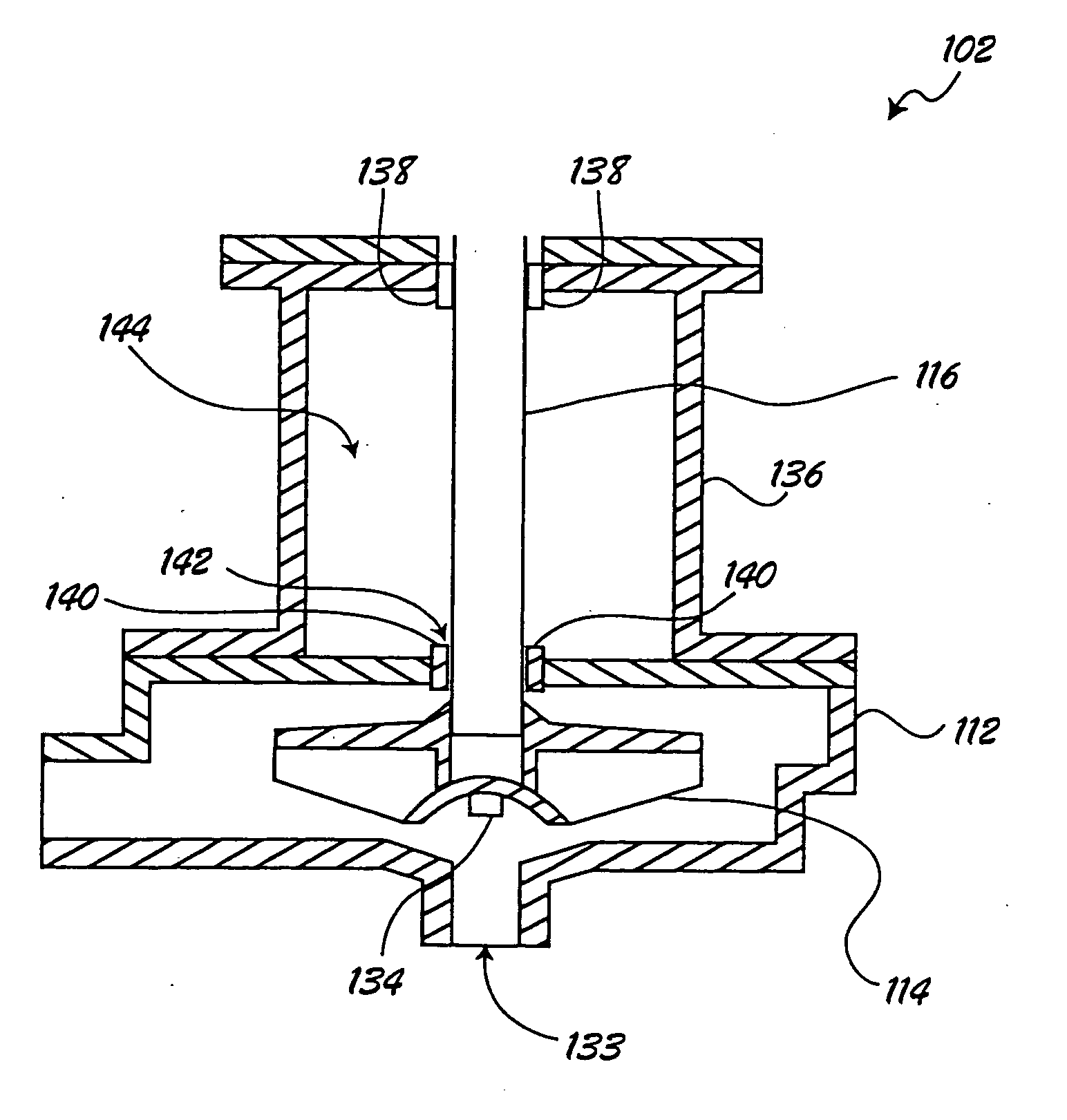
Examples


second embodiment

[0029] Now referring to FIG. 6 in a second embodiment an alternative filtration system 200 features a disposal drain 202 connected to the portal 146 for directing a flow of fluid to a drain / waste treatment area (not shown).

third embodiment

[0030] Referring to FIG. 7 in a third embodiment a filtration system 300 features a return pipe 302 connected directly to the catcher tank.

[0031] In operation, the electric motor 118 is energized thus turning the drive shaft 116 of the pump 102. The impeller 114 is rotated drawing the water and garnet slurry through a system inlet valve 122 into the strainer basket 106. The filter in the strainer basket advantageously allows for retention of large particles while allowing free flow of the garnet and water slurry through the second inlet valve 128 and through the inlet pipe 104 into the pump housing 112. Centrifugal action of the impeller 114 forces the water and garnet slurry into the outlet pipe 108 towards the centrifugal separator 110.

[0032] As the water and garnet slurry is forced into the outlet pipe 108 it also to a limited extent seeps through the gap 142 between the bushing 140 and the drive shaft 116 into the fluid collection space 144 of the fluid collection housing 136. ...


PUM

PropertyMeasurementUnit
diameteraaaaaaaaaa
gravityaaaaaaaaaa
pressureaaaaaaaaaa

Abstract

A garnet filtration system for use with water jet cutting tools is described. The filtration system includes a pump with a fluid collection housing in addition to a pump housing containing an impeller with the drive shaft running through an opening in the pump housing and through the fluid collection housing. A bushing disposed in the pump housing around the drive shaft restricts but does not prevent seepage of fluid between the bushing and the drive shaft into the fluid collection housing. A pipe connected to the fluid collection housing drains the fluid to a catch tank for re-circulating. Alternatively, the fluid is directed to a waste treatment drain. Fluid pumped out of the pump housing is directed to a centrifugal separator for separation of a garnet particulate from a water-based slurry.

Description

CROSS-REFERENCE TO RELATED APPLICATIONS [0001] This application claims the benefit of U.S. Provisional Application No. 60 / 663,440, filed on Mar. 18, 2005. The disclosure of the above application is incorporated herein by reference.FIELD OF THE INVENTION [0002] The present invention relates to abrasive particulate centrifugal filtration systems for use with water jet cutting tools and more particularly to such systems using a sealless pump. BACKGROUND OF THE INVENTION [0003] Water jet tools producing high pressure jets of water containing abrasive particles are used to cut a variety of materials including metals, stone, ceramics, concrete, tile and glass. A water jet tool connects a high pressure water pump to a cutting head in order to produce an ultra-high pressure water jet for discharge through a water jet nozzle. Before the water jet is discharged an abrasive particulate such as garnet particles are added to facilitate the cutting of the material. The water jet containing the ab...

Claims


Application Information

Patent Timeline
Patent Type & Authority Applications(United States)
IPC IPC(8): B01D36/00
CPCB24C9/006B24C11/00Y02P70/10
Inventor TIRAKIAN, EDWARD L.
Owner EBBCO
Learn More