Integrated magnetic/foil bearing and methods for supporting a shaft journal using the same

Inactive Publication Date: 2006-09-21
PERFECT GALAXY INT
View PDF7 Cites 12 Cited by
  • Summary
  • Abstract
  • Description
  • Claims
  • Application Information

AI Technical Summary

Benefits of technology

[0037] structuring and arranging the magnetic field generating device and the foil

Problems solved by technology

The disadvantages or shortcomings of foil bearings include system instability and excessive contact between the shaft and the foil supports during starting, stopping, and peak load conditions.
System instability, which can produce undesirable vibrations, can result from a shaft that is not perfectly cylindrical.
Excessive contact can seriously damage the structural integrity of the bearing.
Disadvantages and shortcomings associated with magnetic bearings, however, include total loss or partial diminution of field strength, e.g., due to a power loss or to the age of the permanent magnets, respectively.
In the case of a total loss of power, failure would be catastrophic.
However, in most cases this is impractical because it would be very expensive.
However, this, too, would be expensive and, further, would require shutting down the system periodically during the replacement operation.
The problem with such a configuration is that a side-by-side arrangement causes the device to be too large and too heavy because each of the side-by-side structures generally requires its own, bulky support structure.
Although, the formula suggests load sharing between the magnetic bearings and the foil bearings, structuring the bearings in series unnecessarily reduces the force density.
First generation foil bearings, comprising foils with uniformly spaced foil bumps, are less effective at limiting air leakage, reducing the hydrodynamic force capacity.

Method used


Image

  • Integrated magnetic/foil bearing and methods for supporting a shaft journal using the same
  • Integrated magnetic/foil bearing and methods for supporting a shaft journal using the same
  • Integrated magnetic/foil bearing and methods for supporting a shaft journal using the same

Examples


Embodiment Construction

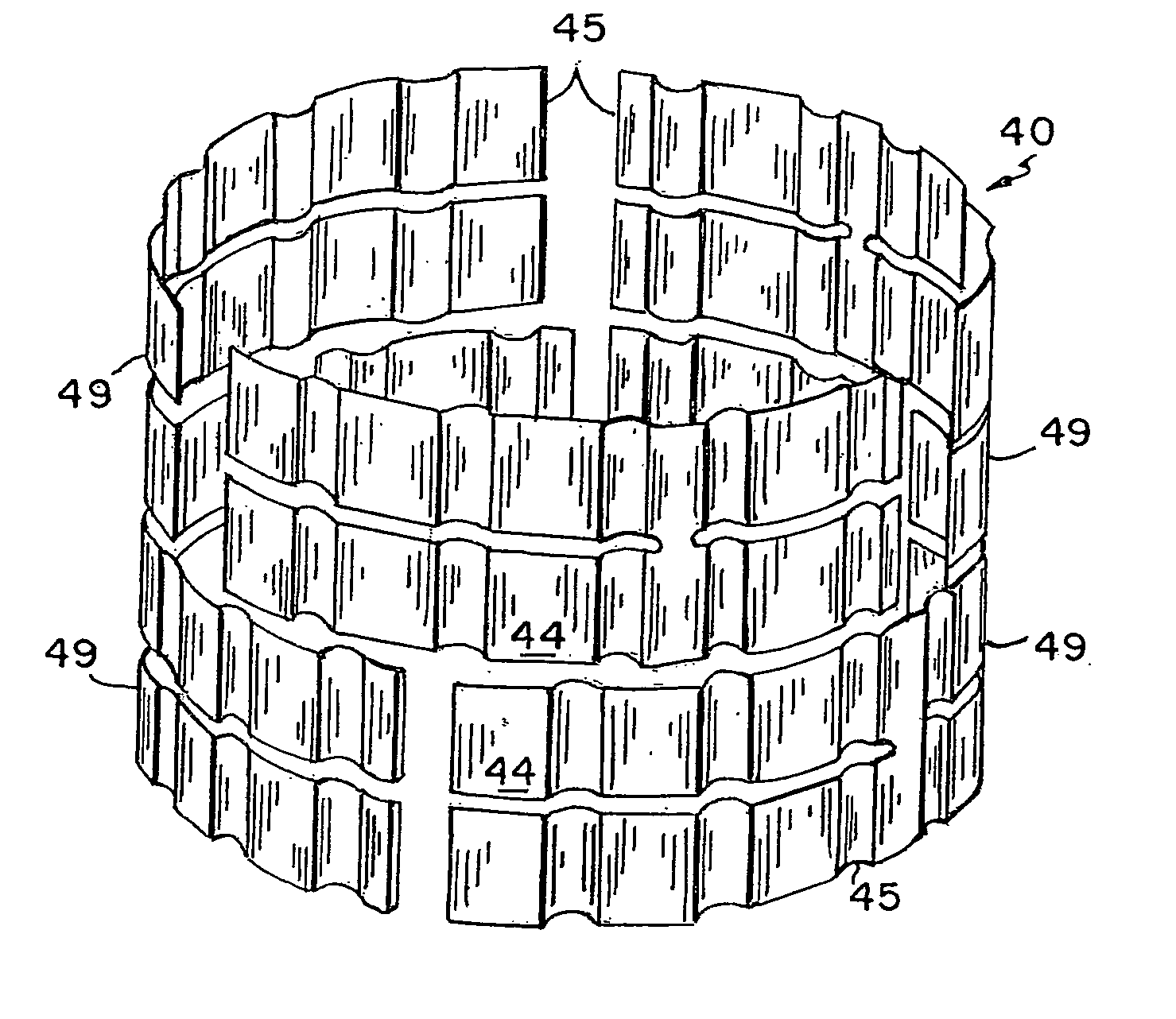
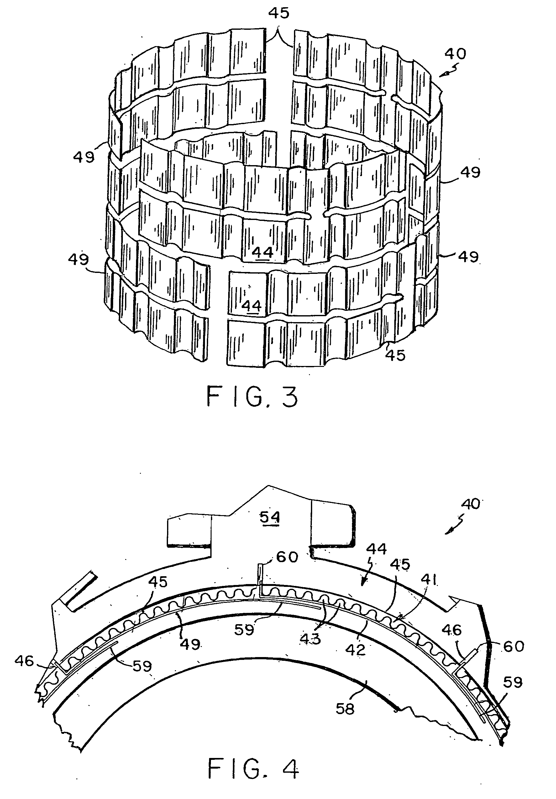
[0047] Referring to FIGS. 3 and 4, a preferred embodiment of a third generation (“3G”), pneumatic foil bearing 40 in accordance with the current state-of-the-art that will be described. Three-G foil bearings 40 enhance bearing performance by providing air support in axial, radial, and circumferential directions.

[0048] In a preferred embodiment, the 3G foil bearing 40 comprises a plurality of foil bearing segments 49 that are structured and arranged to fully circumscribe the entire periphery of the shaft journal 58. Preferably, each foil bearing segment 49 comprises a flexible, bumped foil portion 44 that is fixedly attached to an underside of an outer foil portion 42. More preferably, the bumped foil portion 44 has a sinusoidal or substantially sinusoidal configuration with variable pitch lengths between the crests or troughs of the bump sinusoids 45. Most preferably, each of the outer foil portions 42 is structured and arranged to include an anchor portion 46, which can be removab...


PUM


Abstract

An integrated bearing system (10) for supporting a rotatable shaft journal (58). The system (10) comprises a foil bearing (40) in combination with a magnetic field generating device (50) that produces a magnetic bearing capability to the rotatable shaft journal (58). The foil bearing (40) is integrated into the magnetic field generating device (50), leaving an air gap between the shaft journal (58) and the foil bearing (10). Under normal operating conditions, the magnetic field generating device (50) and the foil bearing (10) each provide a portion of the support to the shaft journal (58).

Description

CROSS-REFERENCE TO RELATED APPLICATIONS [0001] The present invention claims the right of priority of U.S. provisional patent application No. 60 / 602,299, which was filed on Aug. 16, 2004 and which is incorporated in its entirety herein by reference.ACKNOWLEDGEMENT OF FEDERALLY SPONSORED RESEARCH OR DEVELOPMENT [0002] The U.S. Government has a paid-up license in this invention and the right, in limited circumstances, to require the patent owner to license others on reasonable terms as provided for by the terms of Contract Number FA8650-04-C-2493 awarded by the Department of the Air Force.BACKGROUND OF THE INVENTION [0003] 1. Field of the Invention [0004] The present invention relates to devices for supporting a shaft journal and, more specifically, to an integrated bearing that, at lower speeds, is supported primarily by a magnetic bearing and at higher speeds is supported primarily by a foil bearing. [0005] 2. Background Art [0006] The use of magnetic bearings in conjunction with foi...

Claims


Application Information

Patent Timeline
IPC IPC(8): H02K5/16H02K7/08
CPCF16C17/024F16C32/0402F16C32/044F16C41/02H02K7/08H02K7/09F16C2360/23
Inventor FOSHAGE, GERALD K.LOVELACE, EDWARD C.
Owner PERFECT GALAXY INT
Why Eureka
Try Eureka