Control device for high intensity discharge bulb and method of controlling high intensity discharge bulb

a technology of high intensity discharge and control device, which is applied in the direction of electric variable regulation, process and machine control, instruments, etc., can solve the problems of increasing the intensity of light emission and hue (tint) stability and uniformity, and achieves the effects of improving the accuracy of light emission, improving the uniformity of light, and increasing the time of us

a technology of high intensity discharge and control device, which is applied in the direction of electric variable regulation, process and machine control, instruments, etc., can solve the problems of increasing the intensity of light emission and hue (tint) stability and uniformity, and achieves the effects of improving the accuracy of light emission, improving the uniformity of light, and increasing the time of us

US20060208664A1Inactive Publication Date: 2006-09-21SANYO TECNICA

Image

  • Control device for high intensity discharge bulb and method of controlling high intensity discharge bulb
  • Control device for high intensity discharge bulb and method of controlling high intensity discharge bulb
  • Control device for high intensity discharge bulb and method of controlling high intensity discharge bulb

Examples


Embodiment Construction

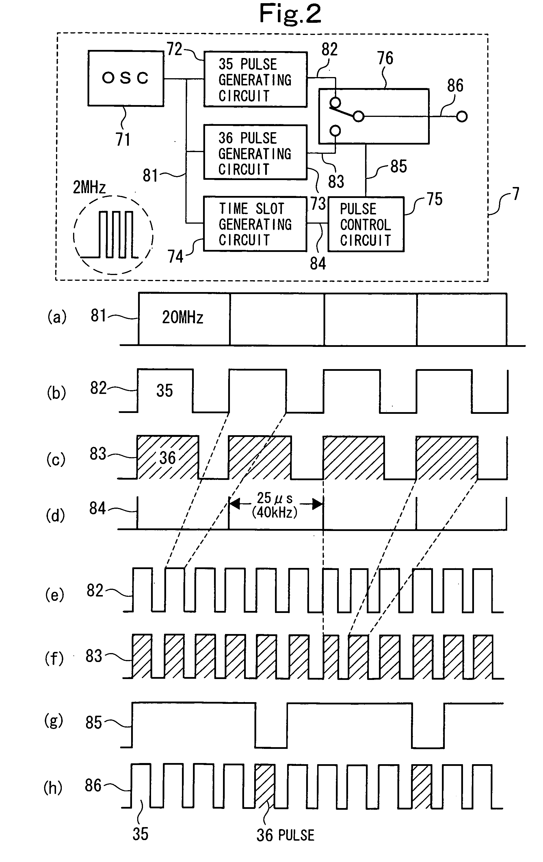
[0047] In the present invention, an ON (duty) time during which a rectangular wave is applied to a HID bulb is controlled by the number of driving pulses or sampling pulses having a pulse width sufficiently smaller than that of the ON time. In the present invention, two types of rectangular waves having different numbers of driving pulses or sampling pulses are provided. By changing the combination of these two different types of rectangular waves, the driving energy of the HID bulb is increased or decreased, thereby supply electric energy to the HID bulb is controlled.

[0048] In the present invention, a two-step method is used. At a first step, an approximate electric power which is close to a target electric power for the HID bulb is set. Then, at a second step, the difference between the approximate electric power and the target electric power is corrected.

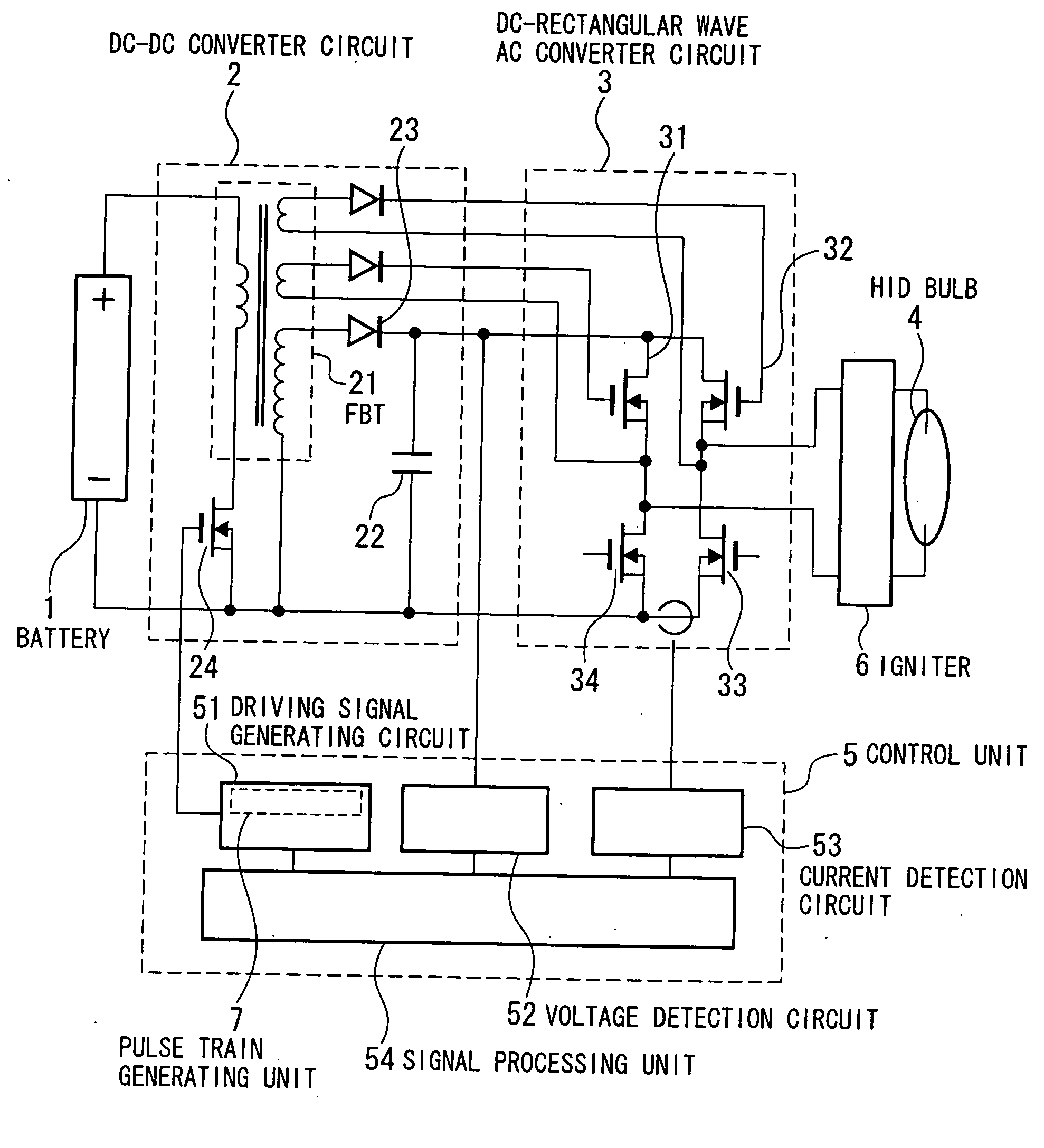
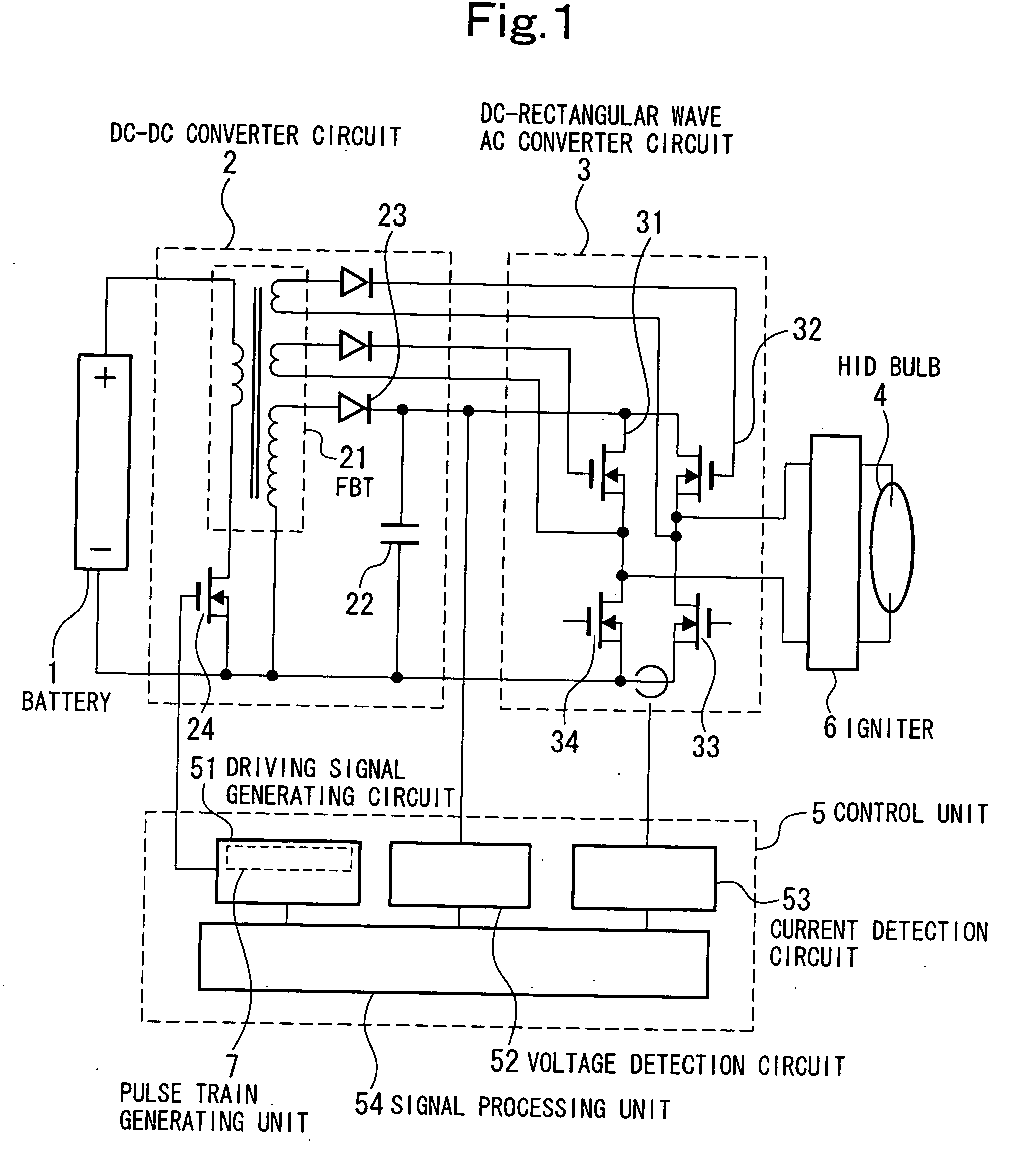
[0049] An embodiment of the present invention will now be described with reference to the drawings.

[0050]FIG. 1 is a circui...


PUM


Abstract

Two types of rectangular waves having different numbers of driving pulses are applied to the HID bulb. By changing the combination of these two different types of rectangular waves to be supplied , the driving energy of the HID bulb is increased or decreased, thereby supply electric energy to the HID bulb is controlled accurately.

Description

BACKGROUND OF THE INVENTION [0001] 1. Field of the Invention [0002] The present invention relates to a power supply device for a high intensity discharge bulb. In particular, the present invention relates to a power supply device for a discharge tube called a high intensity discharge bulb (hereinafter referred to as a HID bulb) for use in vehicles, such as a headlamp for an automobile or motorcycle. [0003] 2. Description of the Related Art [0004] In HID bulbs, there are variations in drive voltage from bulb to bulb. For example, the drive voltage varies from 70(V) to 100(V), i.e., the drive voltage is 85±15(V), which means that the drive voltage varies by about 18%. The emission intensity of a HID bulb is proportional to the electric energy to be applied, i.e., the amount of work (energy). Since HID bulbs have such characteristics, by controlling the currents of individual HID bulbs, the electric energy to be supplied is made constant and variations between products are reduced, whe...

Claims


Application Information

Patent Timeline
21 Sep 2006
Publication
US20060208664A1
IPC
H05B37/02
CPC
H05B41/2883; H05B41/3928; Y02B20/202; Y02B20/00; B26B29/04; B25H3/021
Inventors
OKISHIMA, KIYOSHI