Image display device

a display device and image technology, applied in static indicating devices, non-linear optics, instruments, etc., can solve the problems of insufficient obtaining and inability to obtain uneven electric fields, and achieve the effects of excellent stability, simple and inexpensive construction, and rapid respons

Inactive Publication Date: 2006-09-21
BRIDGESTONE CORP
View PDF9 Cites 127 Cited by
  • Summary
  • Abstract
  • Description
  • Claims
  • Application Information

AI Technical Summary

Benefits of technology

[0014] An object of the first aspect of the invention including the first embodiment and the second embodiment is to provide an image display device having a rapid response in a dry-type device, a simple and inexpensive construction and an excellent stability, which can inhibit an image deterioration due to a particle agglutination during repeated image display operations and can improve a durability.

Problems solved by technology

If the above relations are not satisfied, it is not possible to obtain the uneven electric field having a value larger than the predetermined value.
Therefore, it is not possible to sufficiently obtain the effects such that the image deterioration due to the particle agglutination during the repeated image display operations can be inhibited and the durability can be improved.

Method used


Image

  • Image display device
  • Image display device
  • Image display device

Examples


experiment 1 first embodiment

of the First Aspect of the Invention

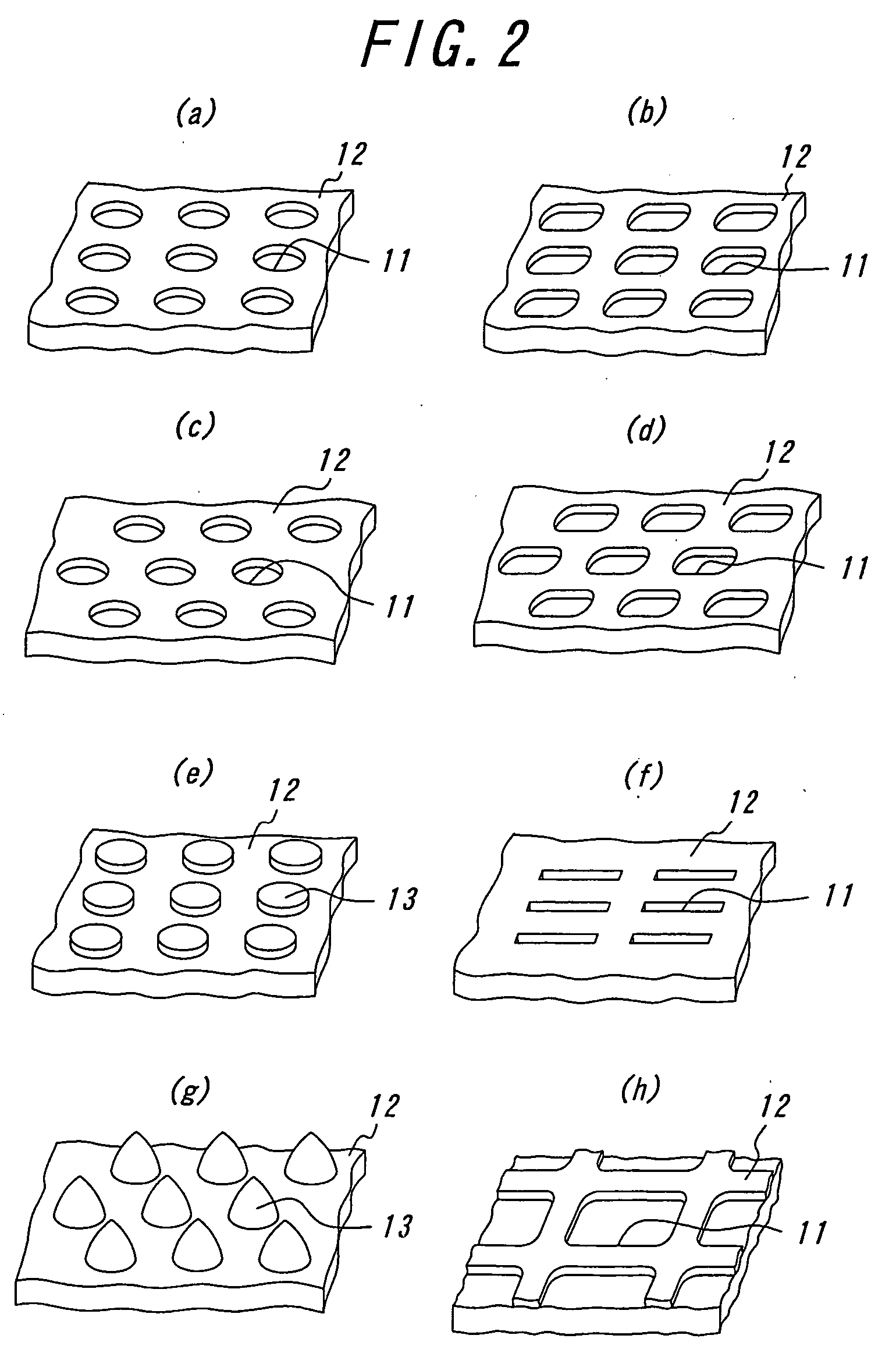
[0250] In the image display device according to the first embodiment of the first aspect of the invention having the construction mentioned above, in order to examine the relation between the maximum average particle size R of the particles and the micro-concave portions and / or the micro-convex portions, the image display devices according to the examples 1-6 were prepared, wherein the micro-concave portions having a shape and an arrangement shown in the following Table 1 with average width W, average height (depth) H and average interval I shown in the following Table 1 were provided to one electrode, and, wherein substrate interval D and maximum average particle size R of the particles were adjusted in the manner shown in the following Table 1. With respect to the thus prepared image display devices according to the examples 1-6, the estimation was performed in such a manner that a rectangular waveform of 4 (kV / mm) was applied for 10 minutes by ...

experiment 2 second embodiment

of the First Aspect of the Invention

[0253] In the image display device according to the second embodiment of the first aspect of the invention having the construction mentioned above, in order to examine the relation between the maximum average size R that is the maximum value among the average particle sizes for two or more kinds of the particles and the micro-cutout holes, the image display devices according to the examples 11-16 were prepared, wherein the micro-cutout holes having a shape and an arrangement shown in the following Table 2 with average width W and average interval I shown in the following Table 2 were provided to one electrode, and, wherein substrate interval d and maximum average particle size R of the particles were adjusted in the manner shown in the following Table 2. With respect to the thus prepared image display devices according to the examples 11-16, the estimation was performed in such a manner that a rectangular waveform of 4 (kV / mm) was applied for 10 m...

experiment 3 first embodiment

of the second Aspect of the Invention

[0256] With respect to respective examples and comparative examples, properties of the particle and functional estimations of the image display device were measured and estimated as follows.

(1) Volume Resistance of the Insulation Member (Resin) for Coating

[0257] The insulation member (resin) for coating was coated to the copper plate, and the measurement was performed according to JIS H 0505-1975.

(2) Charge Potential of the Insulation Member (Resin) for Coating

[0258] A sample for measuring a charge decreasing property was produced by casting only the insulation member (resin) for coating separately. Then, by using CRT2000 apparatus manufactured by QEA, the surface potential, in the case that the surface of the particles was charged by a generation of Corona discharge caused by applying a voltage of 8 kV to a Corona discharge device deployed at a distance of 1 mm from the surface, is measured at 0.3 second after the Corona discharge. In this...


PUM

PropertyMeasurementUnit
particle diameteraaaaaaaaaa
thicknessaaaaaaaaaa
RHaaaaaaaaaa

Abstract

An image display device according to first to third aspects of the invention has an image display panel, in which two or more groups of particles having different colors and different charge characteristics are sealed between two substrates, at least one of two substrates being transparent, and, in which the particles, to which an electrostatic field produced by a pair of electrodes provided on respective substrates is applied, are made to fly and move so as to display an image. In the first aspect of the invention, micro-concave portions and/or micro-convex portions are provided to a part of or an overall of a surface of the electrode (first embodiment) or micro-cutout holes are provided to a part of or an overall of a surface of the electrode (second embodiment). Moreover, in the second aspect of the invention, an insulation member having a volume resistance of not less than 1×10¹² [Ω·cm] is coated thinly on a surface of the substrate to which the particles are contacted so as to provide a thin insulation film, or, an arithmetic average roughness (Ra) and a concave-convex average distance (Sm) of a surface of the substrate, to which the particles are contacted, satisfy the predetermined formulas. Further, in the third aspect of the invention, an image display state is read-out by detecting a fly/move current produced when the particles are flown and moved in a pixel.

Description

TECHNICAL FIELD [0001] The present invention relates to an image display device, which comprises an image display panel enables to repeatedly display or delete images accompanied by flight and movement of particles utilizing Coulomb's force and so on. BACKGROUND ART [0002] As an image display device substitutable for liquid crystal display (LCD), image display devices with the use of technology such as an electrophoresis method, an electro-chromic method, a thermal method, dichroic-particles-rotary method are proposed. [0003] As for these image display device, it is conceivable as inexpensive visual display device of the next generation from a merit having wide field of vision close to normal printed matter, having smaller consumption with LCD, spreading out to a display for portable device, and an electronic paper is expected. Recently, electrophoresis method is proposed that microencapsulate dispersion liquid made up with dispersion particles and coloration solution and dispose th...

Claims


Application Information

Patent Timeline
Patent Type & Authority Applications(United States)
IPC IPC(8): G09G3/34G02F1/1333G02F1/1343G02F1/16756G02F1/1676
CPCG02F1/133707G02F1/134327G02F1/13439G02F1/167G02F2001/1672G02F2001/1674G02F2001/1676G02F2001/1678G09G3/344G09G2300/06G09G2310/0275G09G2360/18G02F1/1676G02F1/1681G02F1/1671G02F1/16756
Inventor NIHEI, NORIOKITANO, HAJIMETAKAGI, KOJIYAKUSHIJI, GAKUMURATA, KAZUYASAKURAI, RYOUIWABUCHI, YOSHINORIYAMAZAKI, HIROTAKAMASUDA, YOSHITOMOHATTORI
Owner BRIDGESTONE CORP
Why Eureka
Try Eureka