Liquid ejection head, image forming apparatus and method of manufacturing liquid ejection head

US20060209137A1Inactive Publication Date: 2006-09-21FUJIFILM CORP

Image

  • Liquid ejection head, image forming apparatus and method of manufacturing liquid ejection head
  • Liquid ejection head, image forming apparatus and method of manufacturing liquid ejection head
  • Liquid ejection head, image forming apparatus and method of manufacturing liquid ejection head

Examples


first embodiment

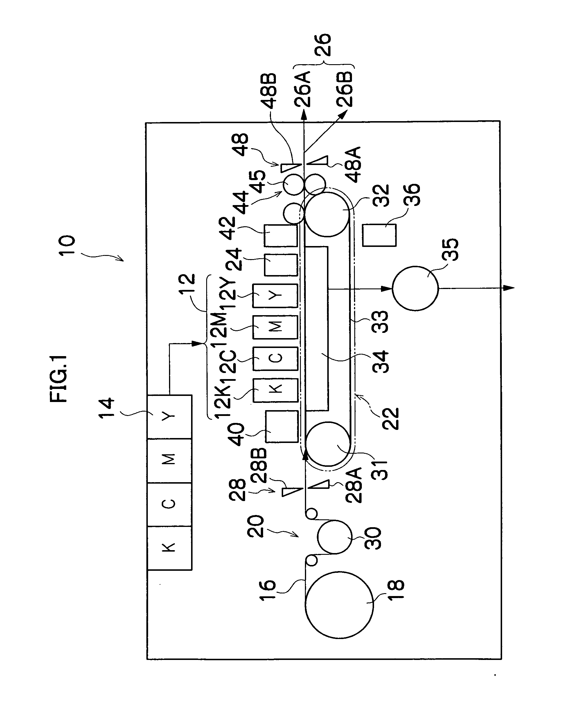
[0033]FIG. 1 is a general schematic drawing of an inkjet recording apparatus forming one embodiment of an image forming apparatus to which the present invention is applied. As shown in FIG. 1, the inkjet recording apparatus 10 comprises: a printing unit 12 having a plurality of print heads 12K, 12C, 12M, and 12Y for ink colors of black (K), cyan (C), magenta (M), and yellow (Y), respectively; an ink storing and loading unit 14 for storing inks of K, C, M and Y to be supplied to the print heads 12K, 12C, 12M, and 12Y; a paper supply unit 18 for supplying recording paper 16; a decurling unit 20 for removing curl in the recording paper 16; a suction belt conveyance unit 22 disposed facing the nozzle face (ink-droplet ejection face) of the print unit 12, for conveying the recording paper 16 while keeping the recording paper 16 flat; a print determination unit 24 for reading the printed result produced by the printing unit 12; and a paper output unit 26 for outputting image-printed recor...

second embodiment

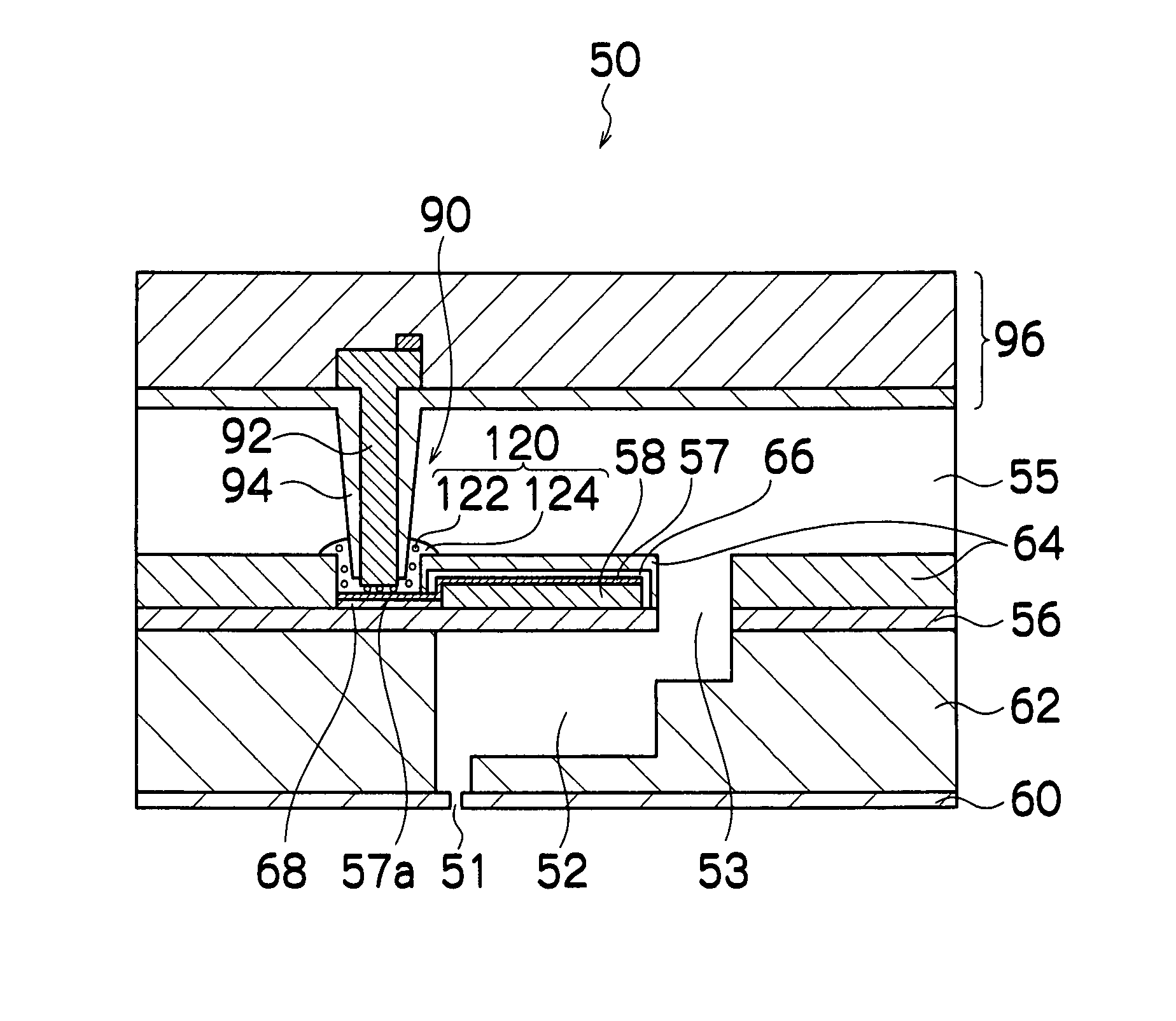
[0098]FIGS. 9A to 9E are illustrative diagrams showing steps for manufacturing the wiring substrate 96 which is composed integrally with the wiring members 90 according to a second embodiment of the present invention.

[0099] Firstly, as shown in FIG. 9A, a substrate 112 formed with a prescribed wiring pattern is prepared. Individual wires 114 corresponding to the individual wires 106 shown in FIGS. 7A to 7F are formed on the substrate 112, and the individual wires 114 are composed so as to provide electrical connections between the conducting members 92 and the switching IC chips 108 (described later).

[0100] Next, as shown in FIG. 9B, the switching IC chips 108 are installed on the substrate 112 in prescribed positions. In the present embodiment, similarly to the first embodiment (see FIG. 8), the switching IC chips 108 are arranged in either end section of the substrate 112.

[0101] Next, as shown in FIG. 9C, hole sections (through holes) 115 corresponding to the individual wires 1...


PUM


Abstract

The liquid ejection head comprises: a plurality of ejection ports which eject liquid; a plurality of pressure chambers which are respectively connected to the ejection ports; a plurality of piezoelectric elements which respectively deform the pressure chambers, the piezoelectric elements being arranged on sides of the pressure chambers opposite to sides thereof where the ejection ports are formed; a common liquid chamber which supplies the liquid to the pressure chambers, the common liquid chamber being arranged on the sides of the pressure chambers opposite to the sides thereof where the ejection ports are formed; a plurality of wiring members which have electrodes for driving the piezoelectric elements, respectively, each of the wiring members being formed in such a manner that at least a portion thereof rises through the common liquid chamber in a direction substantially perpendicular to a plane on which the piezoelectric elements are arranged; and a drive circuit which drives the piezoelectric elements, the drive circuit being arranged on a wall of the common liquid chamber opposite to a side thereof where the piezoelectric elements are arranged, wherein the electrodes and the drive circuit are composed and covered integrally with resin.

Description

BACKGROUND OF THE INVENTION [0001] 1. Field of the Invention [0002] The present invention relates to a liquid ejection head, an image forming apparatus, and a method of manufacturing a liquid ejection head, and more particularly, to technology for disposing the driving wires of piezoelectric elements provided in a liquid ejection head. [0003] 2. Description of the Related Art [0004] There are inkjet type image forming apparatuses comprising print heads (liquid ejection heads) in which nozzles are arranged in a matrix array (see, for example, Japanese Patent Application Publication Nos. 2001-334661 and 2002-166543). The print heads disclosed in Japanese Patent Application Publication Nos. 2001-334661 and 2002-166543 have a common liquid chamber formed on the same side of the pressure chambers as the side on which the nozzles are formed. In these print heads, if drive wires for driving the piezoelectric elements are disposed on the diaphragm, there is a probability that insufficient s...

Claims


Application Information

Patent Timeline
21 Sep 2006
Publication
US20060209137A1
IPC
B41J2/045
CPC
B41J2/14233; B41J2/14282; B41J2002/14459; B41J2002/14491; B41J2202/11; B41J2202/18
Inventors
KOJIMA, TOSHIYA; KACHI, YASUHIKO