Integral viewing and eye imaging system for visual projection systems

a visual projection system and integrated technology, applied in the field of eye tracking devices, can solve the problems of not providing real-time visual images of the eye, not providing complete picture of the eye, and devices that do not track the pupil activity, etc., to achieve the effect of eliminating the alignment and focusing requirements of separate components

Inactive Publication Date: 2006-09-21
AVOTEC
View PDF9 Cites 16 Cited by
  • Summary
  • Abstract
  • Description
  • Claims
  • Application Information

AI Technical Summary

Benefits of technology

[0022] Accordingly; it is an objective of this invention to provide an eye tracking device usable with projection type visual systems. The device should eliminate the alignment and focusing requirements of separate components. The eye tracking device should be impervious to magnetic environments and the output of MRI equipment. The device should not only indicate eye motion, but should also monitor pupil state. The device should be compact enough to monitor a patient located within the bore

Problems solved by technology

Although known detectors provide certain information about eye motion, they have limitations.
In many cases, simple eye motion monitoring does not provide a complete picture.
For example, eye tracking devices that monitor eye-moving muscles typically do not sense pupil action.
Devices that do not track this pupil activity do not provide enough information for many types of medical tests.
Other trackers, such as those that monitor reflected light, may provide some information about pupil action, but do not provide real-time visual images of the eye, itself.
Without this visual image to provide context, electrical eye-position information may be hard to interpret and almost impossible to cross reference.
The problem with this system is that signals from the visual presentation system may be temporarily intermittent or be of such a limited bandwidth as to make illumination of the eye unreliable for the purpose of forming an image of the eye or its structures.
Similar problems stem from reliance on ambient light for illum

Method used


Image

  • Integral viewing and eye imaging system for visual projection systems
  • Integral viewing and eye imaging system for visual projection systems
  • Integral viewing and eye imaging system for visual projection systems

Examples


Embodiment Construction

[0039] It is to be understood that while a certain form of the invention is illustrated, it is not to be limited to the specific form or arrangement of parts herein described and shown. It will be apparent to those skilled in the art that various changes may be made without departing from the scope of the invention and the invention is not to be considered limited to what is shown in the drawings and described in the specification.

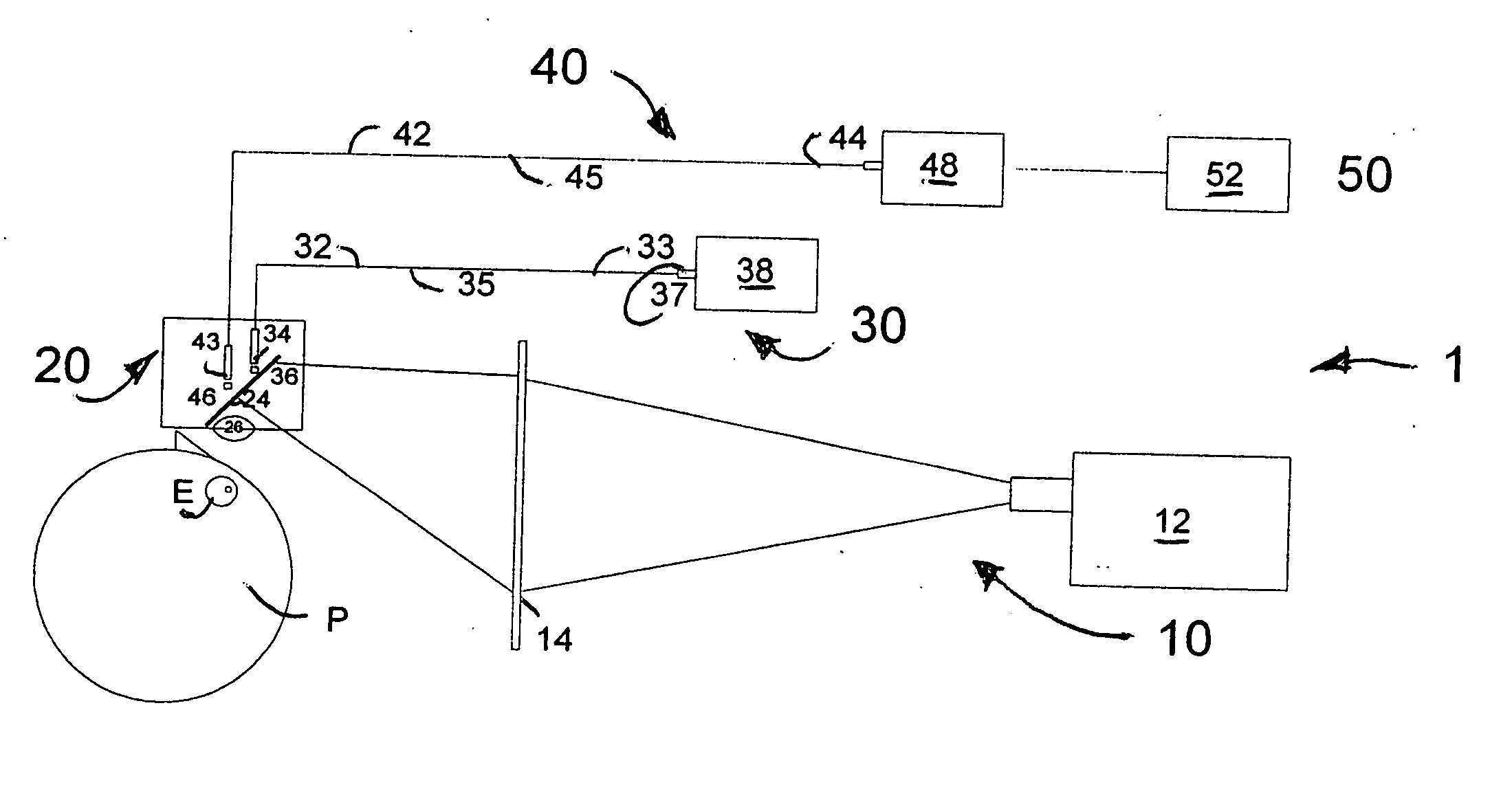
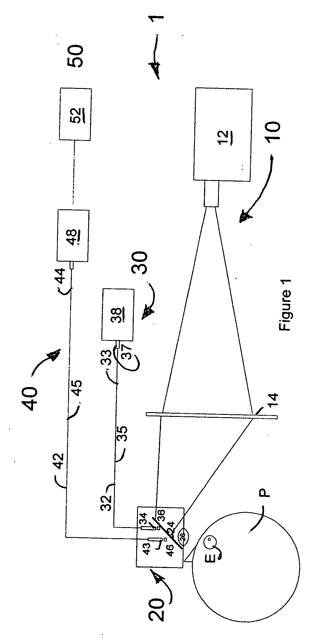
[0040] Now with respect to FIG. 1, the fiber optic eye tracking system 1 of the present invention is shown. The present eye tracking system 1 includes five cooperative subsystems: a visual stimulation subsystem 10, an illumination subsystem 30, a viewing subsystem 20, an image conveyor subsystem 40 and an image processing subsystem 50.

[0041] The visual stimulation subsystem, the illumination subsystem, the imaging receiving subsystem and the viewing subsystem are made from non-magnetic materials and are inert to the electromagnetic forces produced during...


PUM


Abstract

An eye imaging system having an image viewing subsystem for interfacing with an MRI patient. The imagine viewing subsystem incorporates fiber-optic illumination and imaging subsystems that enable automatic eye imaging for eye tracking. The eye imaging system analyzes motion of an patient's eye in response to visual stimuli and includes an image conveyor subsystem, an image receiving subsystem, and an image processing subsystem. The light source utilized to form the reflected images is an independent source of illumination.

Description

RELATED APPLICATIONS [0001] This application is related to U.S. Pat. No. 5,892,566 and U.S. Pat. No. 6,079,829 by the instant inventor. The disclosures of these patents are incorporated by reference.FIELD OF THE INVENTION [0002] This invention is directed to eye tracking devices, particularly, to an eye tracking device suited for analyzing eye-movement of a patient undergoing diagnostic treatment within a magnetic resonance imaging (MRI) apparatus wherein such eye tracking device utilizes an out-of-band light source, and most particularly, wherein such diagnostic treatment may involve visual stimulation. BACKGROUND OF THE INVENTION [0003] Monitoring of eye motion can provide a variety of information. Sleep researchers, for example, use eye motion as an indicator of various sleep stages. Also, persons with limited muscle control can use eye motion to interact with others or to control specialized equipment. Military applications that follow eye motion for targeting purposes or vehicl...

Claims


Application Information

Patent Timeline
IPC IPC(8): A61B13/00A61B3/14
CPCA61B3/113A61B5/055
Inventor BULLWINKEL, PAUL
Owner AVOTEC
Why Eureka
Try Eureka