Multilayer capacitor

a multi-layer capacitor and capacitor technology, applied in the field of multi-layer capacitors, can solve the problems of difficult to reduce the impedance sufficiently, the effect of reducing the impedan

Active Publication Date: 2006-09-21
TDK CORPARATION
View PDF3 Cites 29 Cited by
  • Summary
  • Abstract
  • Description
  • Claims
  • Application Information

AI Technical Summary

Benefits of technology

[0007] With the recent trend toward increase in frequency of the power-supply circuit used in electronic devices, there are needs for further reduction in the equivalent series inductance (ESL) of the multilayer capacitor applied to the power-supply circuit. However, the multilayer capacitor described in Patent Document 1 in...

Problems solved by technology

However, the multilayer capacitor described in Patent Document 1 includes no effective countermeasures for suppressing increase of ...

Method used


Image

  • Multilayer capacitor
  • Multilayer capacitor
  • Multilayer capacitor

Examples


first embodiment

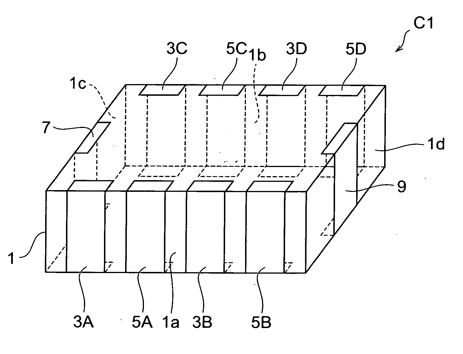
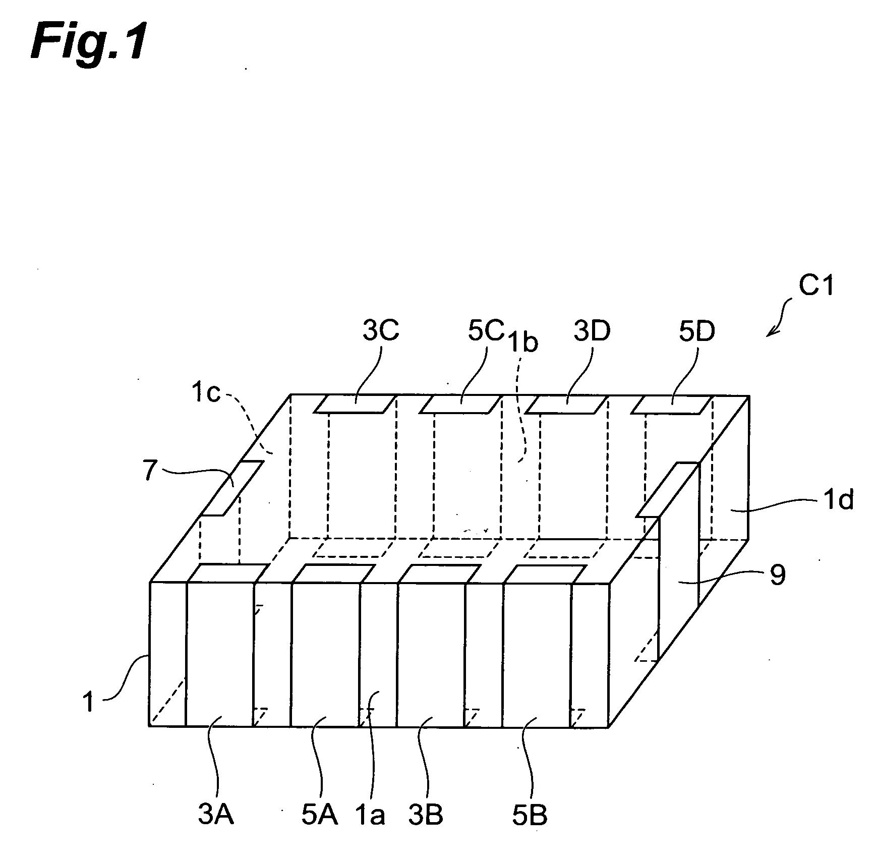
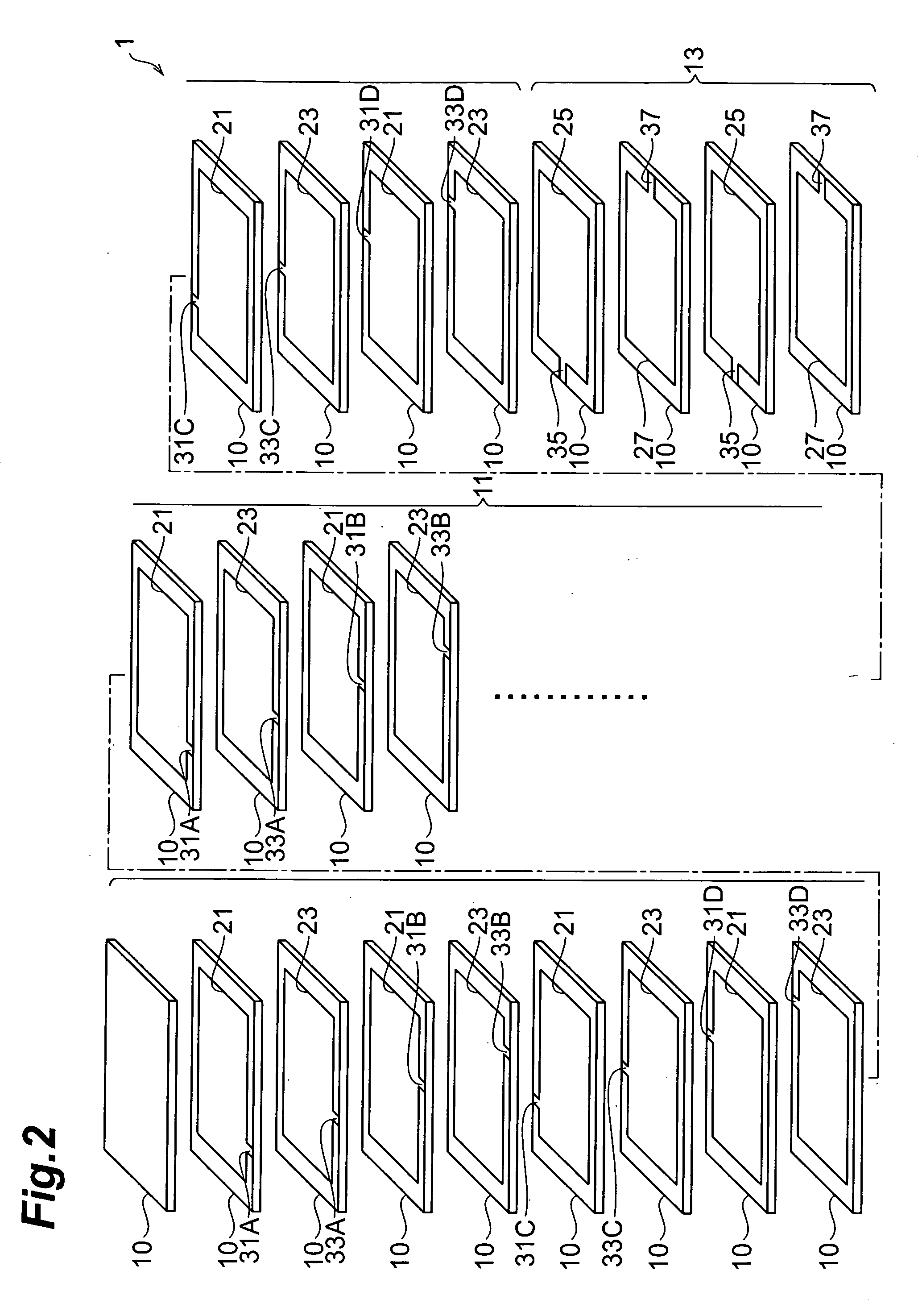
[0027] A configuration of multilayer capacitor C1 according to the first embodiment will be described with reference to FIGS. 1 and 2. FIG. 1 is a perspective view of the multilayer capacitor according to the first embodiment. FIG. 2 is an exploded perspective view of a multilayer body in the multilayer capacitor according to the first embodiment.

[0028] The multilayer capacitor C1, as shown in FIG. 1, is composed of a multilayer body 1 of nearly rectangular parallelepiped shape, and first to fourth terminal electrodes 3A-3D, 5A-5D, 7, and 9 formed on the multilayer body 1. The first and second terminal electrodes 3A-3D, 5A-5D are formed on mutually opposed side faces 1a, 1b of the multilayer body 1. The third and fourth terminal electrodes 7, 9 are formed on mutually opposed side faces 1c, 1d of the multilayer body 1.

[0029] The first terminal electrodes 3A, 3B are formed on the side face 1a of the multilayer body 1. The first terminal electrodes 3C, 3D are formed on the side face ...

second embodiment

[0057] A configuration of a multilayer capacitor according to the second embodiment will be described with reference to FIG. 5. The multilayer capacitor of the second embodiment is different from the multilayer capacitor C1 of the first embodiment in that the second capacitor portion 13 is located between divisions of first capacitor portion 11A, 11B. FIG. 5 is an exploded perspective view of a multilayer body in the multilayer capacitor of the second embodiment.

[0058] The multilayer body 1 in the multilayer capacitor of the second embodiment has first capacitor portion 11A, 11B and second capacitor portion 13. The second capacitor portion 13 is laid so as to be located between divisions of first capacitor portion 11A, 11B, and these capacitor portions 11A, 11B, 13 are integrally laminated to form the multilayer body 1.

[0059] A configuration of the first capacitor portion 11A, 11B will be described. Since the second capacitor portion 13 is located between the divisions of the firs...

third embodiment

[0068] A configuration of a multilayer capacitor according to the third embodiment will be described with reference to FIG. 6. The multilayer capacitor of the third embodiment is different from the multilayer capacitor of the second embodiment in that the laminating number of third internal electrodes 25 is different from the laminating number of fourth internal electrodes 27 in the second capacitor portion 13. FIG. 6 is an exploded perspective view of a multilayer body in the multilayer capacitor of the third embodiment.

[0069] The first capacitor division 11A includes a plurality of dielectric layers 10 (e.g., 5 layers), and a plurality of first and second internal electrodes 21, 23 (e.g., 2 layers each) alternately arranged with dielectric layer 10 in between. The first and second internal electrodes 21, 23 are laminated along a direction in which the first and second capacitor portions 11A, 11B, 13 are laminated (which will be referred to hereinafter as a laminating direction). ...


PUM


Abstract

A multilayer capacitor comprises a multilayer body in which a plurality of dielectric layers and a plurality of internal electrodes are alternately laminated, and a plurality of terminal electrodes formed on side faces of the multilayer body. The multilayer body has a first capacitor portion and a second capacitor portion. The first capacitor portion includes first and second internal electrodes as the internal electrodes. The second capacitor portion includes third and fourth internal electrodes as the internal electrodes. Each of the first to fourth internal electrodes is electrically connected through a lead conductor or through lead conductors to one or more corresponding terminal electrodes among the first to fourth terminal electrodes. The first and second capacitor portions have their respective capacitances different from each other.

Description

BACKGROUND OF THE INVENTION [0001] 1. Field of the Invention [0002] The present invention relates to a multilayer capacitor. [0003] 2. Related Background Art [0004] An example of the known multilayer capacitors of this type is one having a multilayer body in which a plurality of dielectric layers and a plurality of internal electrodes are alternately laminated, and a plurality of terminal electrodes formed on the multilayer body (e.g., reference is made to Patent Document 1). [0005] Incidentally, a multilayer capacitor to be connected to a power-supply circuit or the like of an electronic device in order to remove noise is demanded to demonstrate the effect of removing noise in a wide frequency band. In order to effectively remove noise in a wide frequency band, the multilayer capacitor of this type is required to have low impedance over the wide band. [0006] Patent Document 1 discloses a multilayer capacitor in which two capacitors with different capacitances obtained by division o...

Claims


Application Information

Patent Timeline
IPC IPC(8): H01G4/005
CPCH01G4/232H01G4/30F16B7/0486F16L3/085F16L21/002
Inventor TOGASHI, MASAAKI
Owner TDK CORPARATION
Why Eureka
Try Eureka