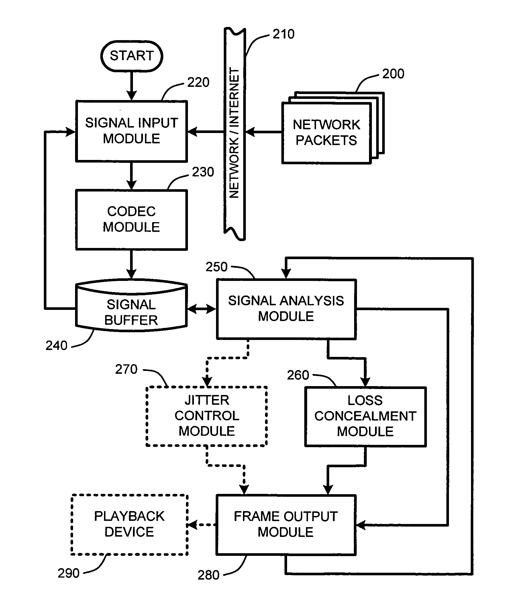
Packet loss concealment for overlapped transform codecs

a transform codec and packet loss technology, applied in the field of packet loss concealment for overlapped transform codecs, can solve the problems of lag or delay in communication, receivers cannot wait for packets to be retransmitted, correctly ordered, or corrected without causing undue, and packet loss loss. , the effect of reducing the bandwidth of the transmission system

Inactive Publication Date: 2006-09-21
MICROSOFT TECH LICENSING LLC
View PDF3 Cites 33 Cited by
  • Summary
  • Abstract
  • Description
  • Claims
  • Application Information

AI Technical Summary

Benefits of technology

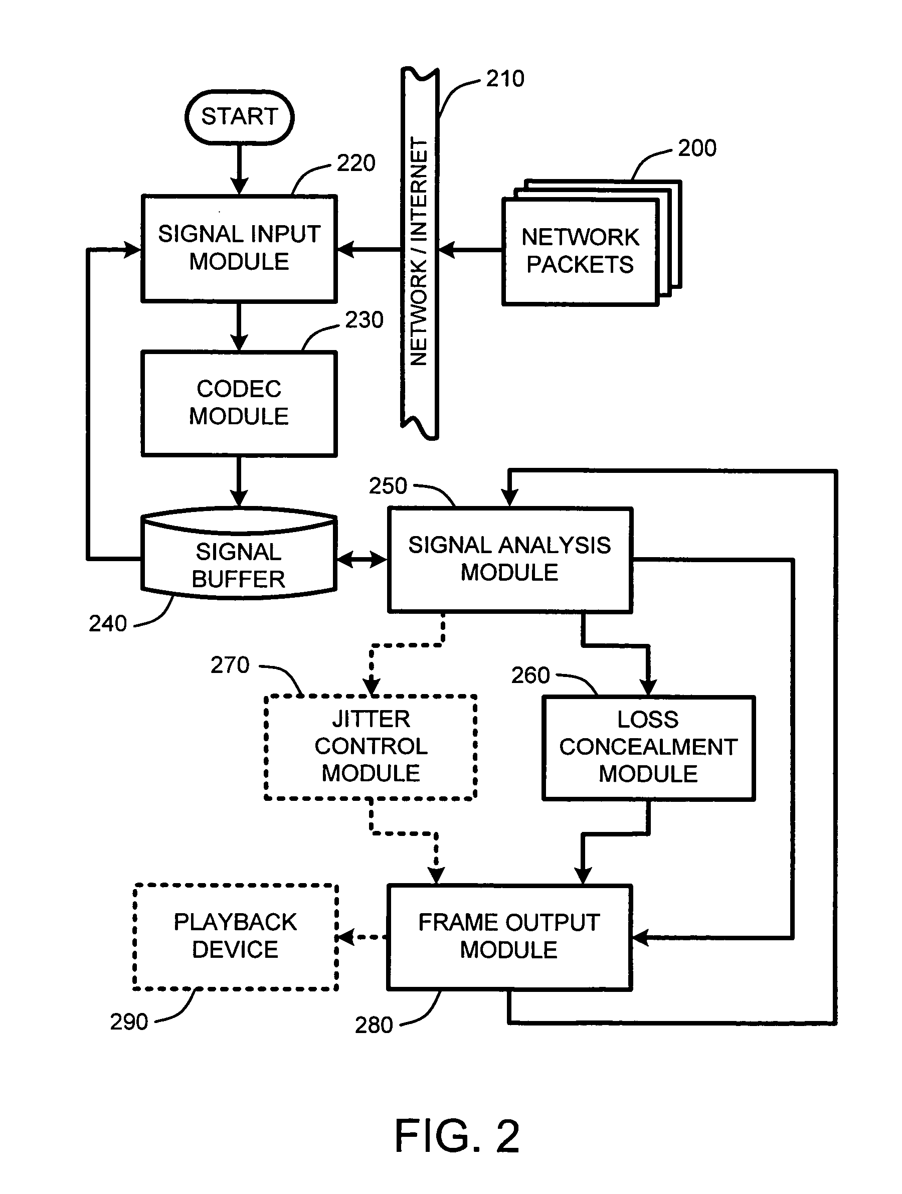
[0015] In general, the adaptive packet loss concealer operates to “hide” lost packets from the listener by exploiting information available from partially received samples to reconstruct missing signal segments. The adaptive packet loss concealer provides this capability by determining an optimized packet loss concealment solution for particular lost packets. This optimized solution is found by solving an underdetermined system of linear equations representing partially received samples while minimizing a computed error based on a model of the signal obtained from neighboring blocks or frames received by the decoder.

Problems solved by technology

Conventional packet communication systems, such as the Internet or other broadcast networks, are typically lossy.
Further, any delay in delivery time is usually variable.
However, for near real-time applications, such as, for example, voice-based communications systems across packet-based networks, the receiver can not wait for packets to be retransmitted, correctly ordered, or corrected without causing undue, and noticeable, lag or delay in the communication.
Unfortunately, as the length of the buffer increases, playback of the signal increasingly lags real-time.
However, in systems such as real-time or two-way conversations, temporal lag resulting from the use of such buffers becomes increasing apparent, and undesirable, as the buffer length increases.
Unfortunately, the use of temporal stretching and compression techniques for frames in an audio signal often results in audible artifacts which may be objectionable to the human listener.
As noted above, packet loss may occur when overly delayed packets are not received in time for playback.
Similarly, packet loss may also occur simply because the packet was never received.
Unfortunately, in the case of overlapped transform coders, the composite signal segments generated by conventional packet loss concealment techniques fail to fully exploit the partial information available from partially received neighboring samples (i.e., packets on either or both sides of a lost data packet).
However, if the information about any one of the blocks of N coefficients is lost, a total of 2N samples—spanning the lost coefficients—cannot be reconstructed.
Unfortunately, the result is typically that there are noticeable artifacts in the reconstructed signal.

Method used


Image

  • Packet loss concealment for overlapped transform codecs
  • Packet loss concealment for overlapped transform codecs
  • Packet loss concealment for overlapped transform codecs

Examples


Embodiment Construction

[0025] In the following detailed description, reference is made to the accompanying drawings, which form a part hereof, and in which is shown by way of illustration specific embodiments in which the invention may be practiced. It is understood that other embodiments may be utilized and structural changes may be made without departing from the scope of the present invention.

1.0 Exemplary Operating Environment:

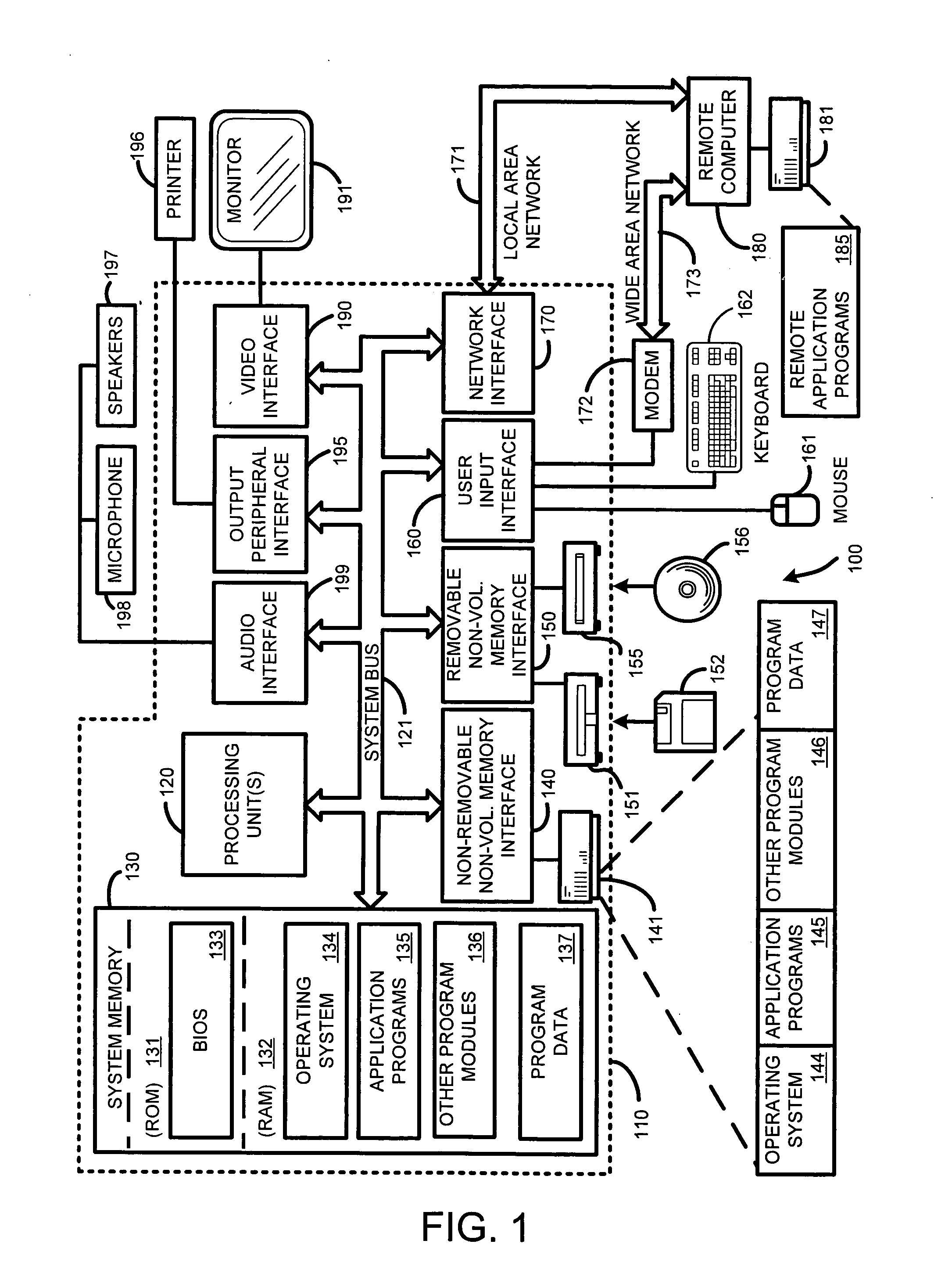
[0026]FIG. 1 illustrates an example of a suitable computing system environment 100 on which the invention may be implemented. The computing system environment 100 is only one example of a suitable computing environment and is not intended to suggest any limitation as to the scope of use or functionality of the invention. Neither should the computing environment 100 be interpreted as having any dependency or requirement relating to any one or combination of components illustrated in the exemplary operating environment 100.

[0027] The invention is operational with numerous othe...


PUM


Abstract

Real-time packet-based audio communications over packet-based networks frequently results in the loss of one or more packets during any given communication session. The real-time nature of such communications precludes retransmission of lost packets due to the unacceptable delays that would result. Consequently, packet loss concealment methods are employed to “hide” lost packets from the listener. Unfortunately, conventional loss concealment methods, such as packet repetition or stretch/overlap methods, do not fully exploit information available from partially received samples. Therefore, when a single frame of N coefficients is lost, 2N samples are only partially reconstructed, thereby degrading the reconstructed signal. To address this problem, an optimized packet loss concealment solution is identified for particular lost packets by solving an underdetermined system of linear equations representing partially received samples while minimizing a computed error based on a model of the signal obtained from neighboring blocks or frames received by the decoder.

Description

CROSS REFERENCE TO RELATED APPLICATIONS: [0001] This application claims the benefit under Title 35, U.S. Code, Section 119(e), of a previously filed U.S. Provisional Patent Application, Ser. No. 60 / 657,831 filed on Mar. 1, 2005, by Florencio, et al., and entitled “PACKET LOSS CONCEALMENT FOR OVERLAPPED TRANSFORM CODECS.BACKGROUND [0002] 1. Technical Field [0003] The invention is related to receipt and playback of packet-based audio signals, and in particular, to a system and method for providing improved packet loss concealment for overlapped transform encoded signals broadcast across a packet-based network or communications channel. [0004] 2. Related Art [0005] Conventional packet communication systems, such as the Internet or other broadcast networks, are typically lossy. In other words, not every transmitted packet can be guaranteed to be delivered either error free, on time, or even in the correct sequence. Further, any delay in delivery time is usually variable. If the receiver...

Claims


Application Information

Patent Timeline
Patent Type & Authority Applications(United States)
IPC IPC(8): H04N7/12
CPCG10L19/005G10L19/0212
Inventor FLORENCIO, DINEI A.CHOU, PHILIP A.
Owner MICROSOFT TECH LICENSING LLC
Why Eureka
Try Eureka