Frequency offset tracking

Inactive Publication Date: 2006-09-21
KK TOSHIBA
View PDF4 Cites 114 Cited by
  • Summary
  • Abstract
  • Description
  • Claims
  • Application Information

AI Technical Summary

Benefits of technology

[0016] Various methods can be used to determine the frequency offset component from each channel. Preferred methods include differential phase

Problems solved by technology

These frequency offsets are typically caused by inaccuracies in the receiver's phase lock loop tracking the received signal's carrier frequency, as well as temperature variations in local oscillators.
If these frequency offsets are not corrected, phase errors in the estimation of data symbols will occur, which degrades performance.
The frequency offset on each subcarrier is typically caused by a combination of an error in the receiver generated carri

Method used


Image

  • Frequency offset tracking
  • Frequency offset tracking
  • Frequency offset tracking

Examples


Embodiment Construction

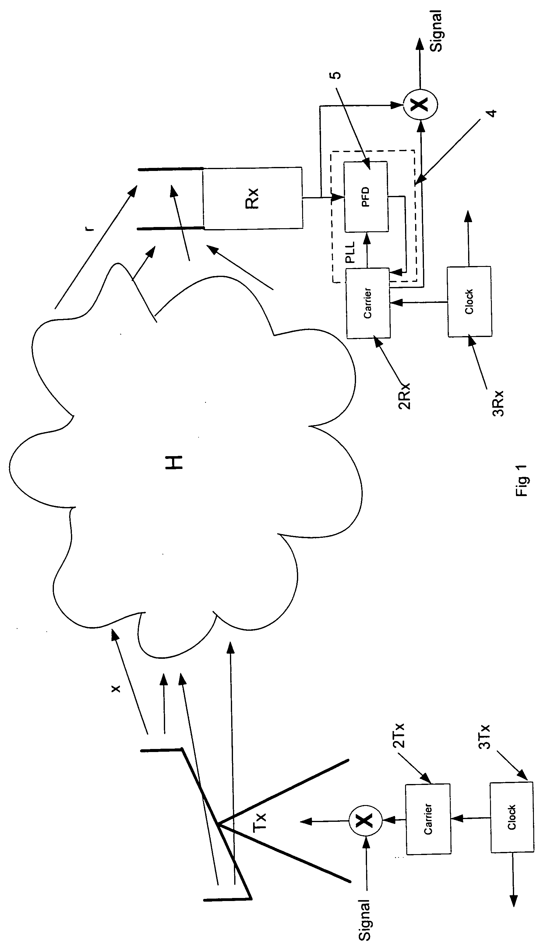
[0033]FIG. 1 shows a wireless communications system having a transmitter Tx, a receiver Rx and an air interface channel H. At the transmitter an information signal or data is multiplied by a carrier frequency as is known, in order to produce symbols which are then transmitted. The carrier signal is generated by a local oscillator 2Tx, and the transmitter also comprises a local system clock 3Tx for use in other signal processing. The transmitted symbols x travel through the air interface channel H and are received by the receiver Rx as symbols r which have been modified by the effects of the channel H and noise. The received symbols r are then multiplied by the carrier frequency again in order to recover the original data signal.

[0034] The carrier signal is generated by a local oscillator 2Rx, and the receiver also comprises a local system clock 3Rx for use in other signal processing. Phase differences or lack of synchronicity between the transmitter and receiver can largely be reso...


PUM


Abstract

The present invention relates to estimating and correcting for frequency offset errors in wireless receivers, and is particularly but not exclusively related to MIMO WLAN applications. The present invention provides an improved method of tracking receiver frequency offsets in a receiver for MIMO systems. These receiver based frequency offset components are caused by errors or inaccuracies in various receiver sub-systems such as phase lock loops or carrier frequency oscillator error, and sampling clock rate errors. The frequency offsets due to each of a number of receiver sub-systems are estimated by monitoring frequency offsets on a number of channels or subcarriers (such as OFDM pilot channels) on different frequencies. These channel frequency offsets are preferably estimated by detecting the phase rotation between adjacent pilot symbols on each respective channel. They are then weighted according to a quality parameter of the estimates, which corresponds to their accuracy. An example of a quality parameter is the effective SNR of the respective channels, or preferably the error variance of the phase rotation. In an embodiment the quality parameter is or is proportional to ∥Hx∥2. The weighted channel frequency offsets are then used to determine one or more receiver sub-system frequency offset components. For example a least squares line fit analysis can be performed.

Description

FIELD OF THE INVENTION [0001] The present invention relates to estimating and correcting for frequency offset errors in wireless receivers, and is particularly but not exclusively related to MIMO WLAN applications. BACKGROUND OF THE INVENTION [0002] In wireless communication systems, small differences between frequency of a transmitted signal's carrier frequency and the receiver's locally generated carrier frequency will effect the accuracy of the received signal, and should therefore be corrected. These frequency offsets are typically caused by inaccuracies in the receiver's phase lock loop tracking the received signal's carrier frequency, as well as temperature variations in local oscillators. If these frequency offsets are not corrected, phase errors in the estimation of data symbols will occur, which degrades performance. [0003] An increasingly important wireless technology is orthogonal frequency division multiplexing (OFDM) which is robust in noisy and rapidly changing environ...

Claims


Application Information

Patent Timeline
IPC IPC(8): H04L1/02H04J99/00H04L27/00H04L27/26
CPCH04L27/2657H04L2027/0032H04L2027/0065H04L2027/0075H04L27/2675
Inventor SANDELL, MAGNUS STIG TORSTENMCNAMARA, DARREN PHILLIPPARKER, STEVE CARL JAMIESON
Owner KK TOSHIBA
Why Eureka
Try Eureka