Hermetically sealed compressor
a compressor and hermetically sealed technology, applied in the field of hermetically sealed compressors, can solve the problems of reducing the cooling efficiency of hermetically sealed rotary compressors, and achieve the effect of reducing the oil pressur
- Summary
- Abstract
- Description
- Claims
- Application Information
AI Technical Summary
Benefits of technology
Problems solved by technology
Method used
Image
Examples
first embodiment
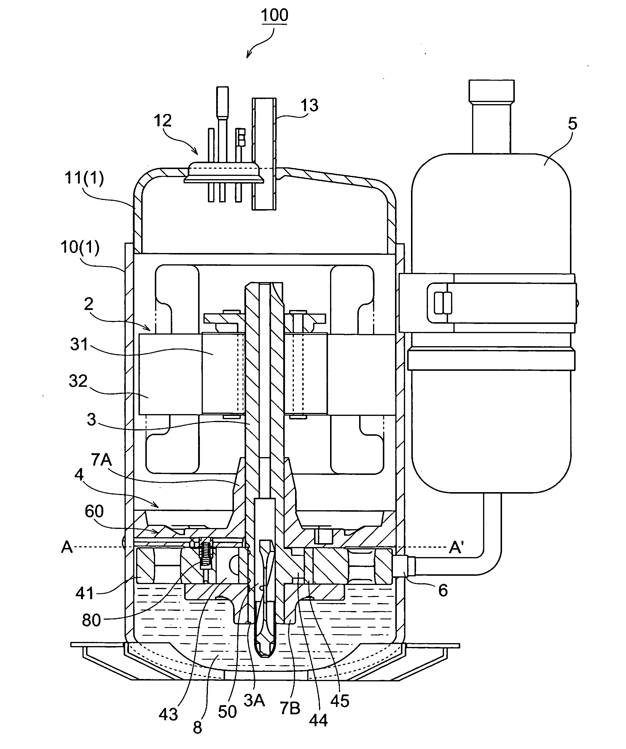
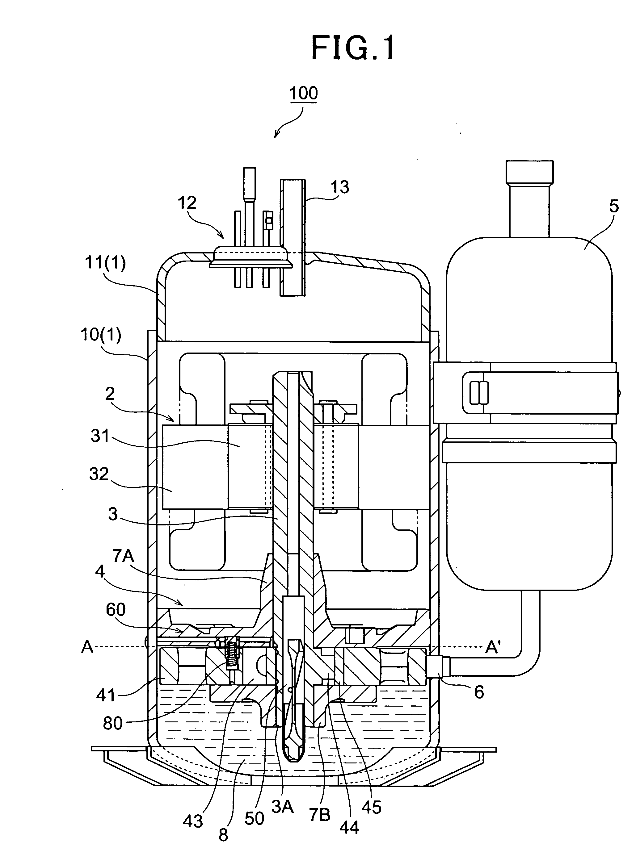
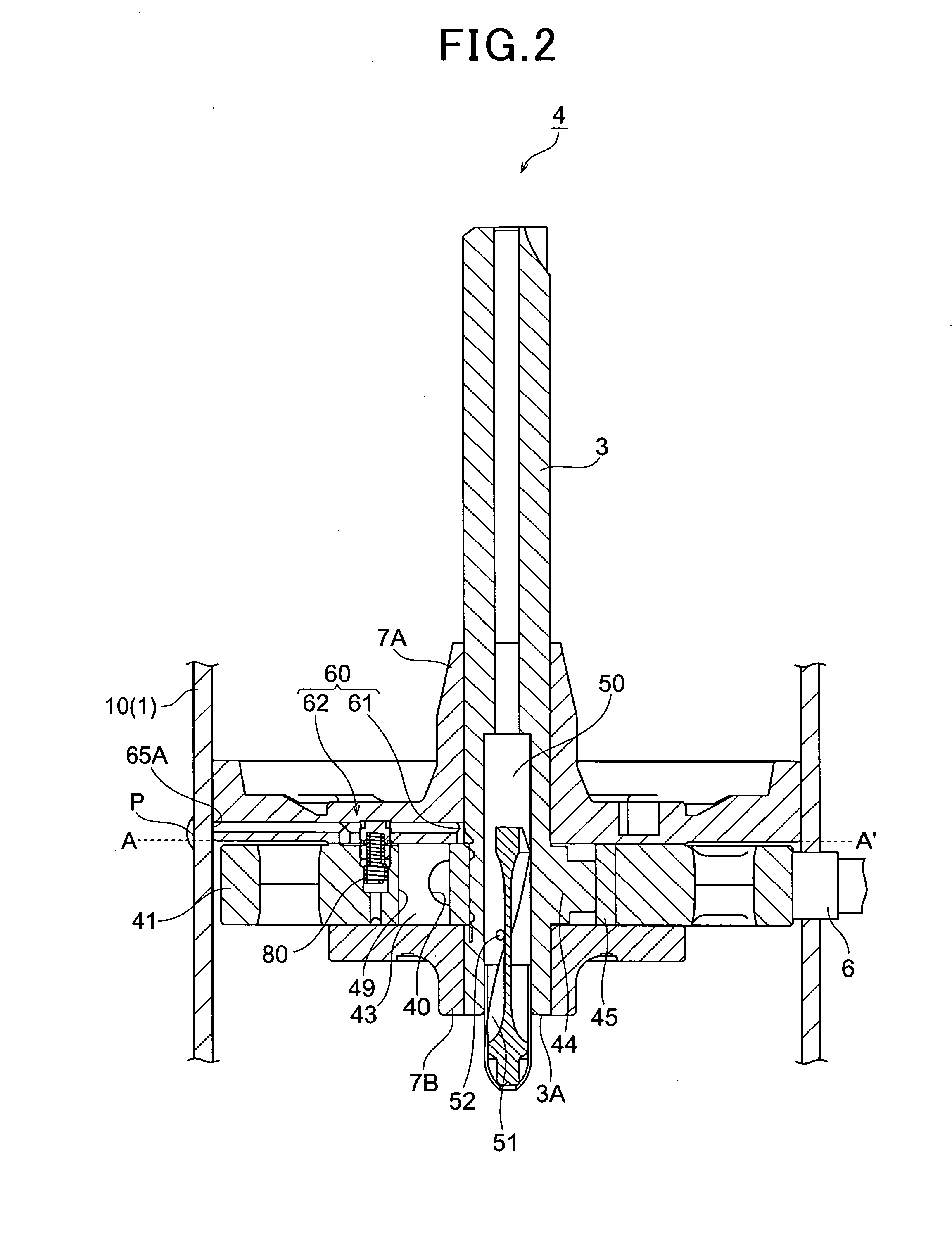
[0031]FIG. 1 is a longitudinally-sectional view showing a hermetically sealed rotary compressor according to a first embodiment of the present invention, and FIG. 2 is an enlarged longitudinally-sectional view of a rotary compressing element. The hermetically sealed rotary compressor 100 constructs a refrigerating unit by connecting a condenser for refrigerant and an evaporator for refrigerant through a pipe. As shown in FIG. 1, the hermetically sealed rotary compressor 100 has a hermetically sealed container 1, an electrically-driven element 2 accommodated at the upper side of the hermetically sealed container 1, and a rotary compressing element 4 accommodated at the lower side of the hermetically sealed container 1. The rotary compressing element 4 is driven by a crank shaft 3 of the electrically-driven element 2 to compress refrigerant.
[0032] The hermetically sealed container 1 is equipped with a cylindrical shell portion 10, and an end cap 11 fixed to the shell portion 10 by ar...
second embodiment
[0066]FIG. 5 is a longitudinally-sectional view showing a hermetically sealed rotary compressor according to a second embodiment of the present invention, and FIG. 6 is an enlarged longitudinally-sectional view showing a rotary compressing element. The hermetically sealed rotary compressor 100A constitutes a refrigerating unit by connecting a refrigerant condenser and a refrigerant evaporator through a pipe. As in the case of the hermetically sealed rotary compressor 100, as shown in FIG. 5, the hermetically sealed rotary compressor 100A has a hermetically sealed container 1, an electrically-driven element 2 is accommodated at the upper side of the hermetically sealed container 1, and a rotary compressing element 4 that is driven by a crank shaft 3 of the electrically-driven element 2 to compress the refrigerant is accommodated at the lower side of the hermetically sealed container 1.
[0067] As shown in FIGS. 5 and 6, the hermetically rotary compressor 100A of this embodiment has th...
third embodiment
[0084]FIG. 9 is a diagram showing the construction of a refrigerating circuit 1200 according to an embodiment. As shown in FIG. 9, the refrigerating circuit 1200 (refrigerating cycle) comprises a hermetically sealed rotary compressor 100B, a condenser 1110, an expansion valve 1120 and an evaporator 1130 that are connected to one another in this order through a refrigerant pipe 1140. In this refrigerating circuit 1200, high-temperature and high-pressure gas refrigerant compressed in the hermetically sealed rotary compressor 100B radiates heat in the condenser 1110 and is condensed and liquefied. The refrigerant thus liquefied is reduced in pressure by the expansion valve 1120, and absorbs heat from the outside heat in the evaporator 1130 to thereby cool the surrounding of the evaporator 1130. Thereafter, the liquefied refrigerant is stocked in an accumulator (not shown), and the gas refrigerant is returned to the hermetically sealed rotary compressor 100B.
[0085]FIG. 10 is a longitud...
PUM
 Abstract
Description
Claims
Application Information
 - R&D
- Intellectual Property
- Life Sciences
- Materials
- Tech Scout
- Unparalleled Data Quality
- Higher Quality Content
- 60% Fewer Hallucinations
Browse by: Latest US Patents, China's latest patents, Technical Efficacy Thesaurus, Application Domain, Technology Topic, Popular Technical Reports.
© 2025 PatSnap. All rights reserved.Legal|Privacy policy|Modern Slavery Act Transparency Statement|Sitemap|About US| Contact US: help@patsnap.com


