Junction block

Active Publication Date: 2006-09-21
YAZAKI CORP
View PDF5 Cites 18 Cited by
  • Summary
  • Abstract
  • Description
  • Claims
  • Application Information

AI Technical Summary

Benefits of technology

[0043] With the construction described above, the combination of the respective components is carried out in the vicinity of the mount, which i

Problems solved by technology

However, in the conventional structure described above, since the components such as the wiring board 75, circuit boards 76 and 77, connectors 78 and 79, fuse mount 80 and relay mount 81 are received in a space formed being surrounded by the respective covers 72-74, therefore a dead space is easily formed, causing a problem that the junction block 71 is forced to increase its size or causing difficulty in achieving high density circuit connection.
Further, in order to electrically connect the components such as the wiring board 75, circuit boards 76

Method used


Image

  • Junction block
  • Junction block
  • Junction block

Examples


Embodiment Construction

[0068] In the following, the preferred embodiments of the present invention will be explained in detail with reference to the attached drawings.

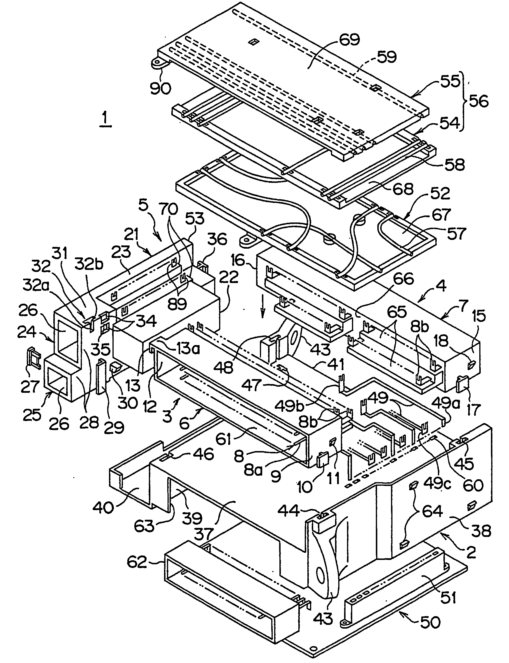
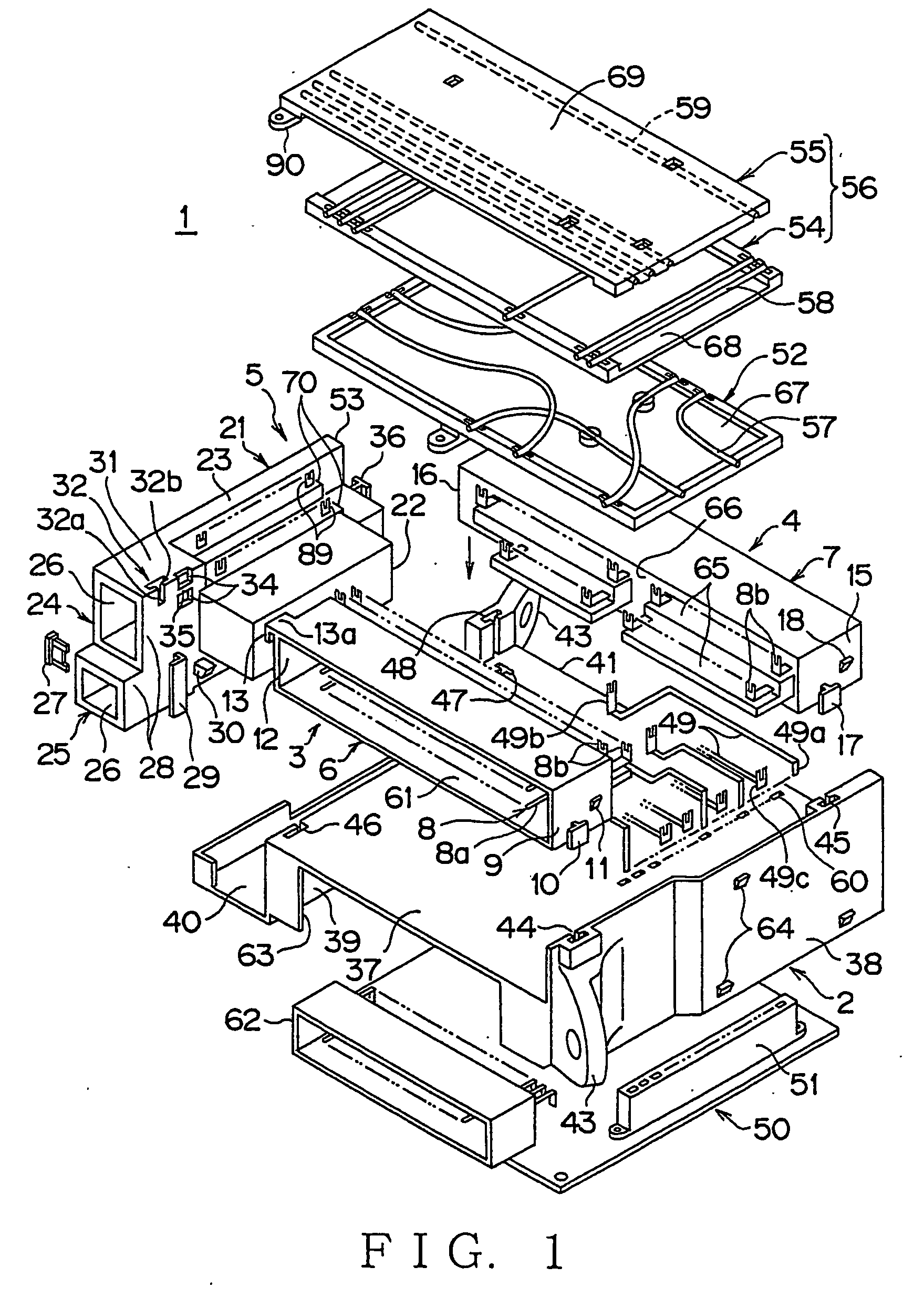
[0069]FIG. 1 shows a preferred embodiment of a junction block according to the present invention.

[0070] The junction block 1 includes: an inner cover 2 made, of synthetic resin; a pair of connector blocks 3, 4 situated right and left to be slidingly engaged with and fixed to the inner cover 2 from above; a power block 5 situated on one side to be slidingly engaged with and fixed to the inner cover 2 from above; a plurality of busbars 49 mounted on the inner cover 2 between both connector blocks 3, 4; and a random wiring module (wiring module) 52 and a cross wiring module (wiring module) 56 both to be piled on the inner cover 2 from above between both connector blocks 3, 4 and to be connected to the connector blocks 3, 4, power block 5 and busbars 49.

[0071] Each connector block 3, 4 includes a housing 6, 7 made of synthetic resin and termi...


PUM


Abstract

A junction block, in which the total structure and circuit connection structure are compact and highly dense, respectively, is provided. A junction block 1 includes: an inner cover 2; connector blocks 3, 4 and a power block 5 disposed outside the inner cover; and busbars 49 and wiring module disposed being piled up within a space surrounded by the connector blocks and the power block, wherein terminals 8b of the connector blocks, terminals 89 of the power block and terminals 49b, 49c of the busbars are connected to the wiring module. The wiring module consists of a random wiring module 52 and a cross wiring module 56. The terminals 8b, 49c, 89 are connected to ends of the wiring modules 52, 56 and part of the terminals 49b of the busbars 49 are connected to a middle part of the random wiring module 52 situated as a lower layer in the space. The terminals 8b, 89 are arranged in a plurality of steps, wherein the terminals arranged in a lower step are connected to a narrow lower wiring module 52 while the terminals arranged in an upper step are connected to a wide upper wiring module 56.

Description

TECHNICAL FIELD [0001] The present invention relates to a junction block, in which constitutional components such as connector blocks, a fuse block and a wiring module are combined to an inner cover. BACKGROUND ART [0002]FIG. 23 shows an example of a conventional junction block (for example, referring to Japanese Patent Application Laid-Open No. H11-27829, particularly page 3 and FIG. 2 thereof). [0003] The junction block 71 includes components such as a wiring board 75, busbar circuit 76 board, printed circuit board 77, connectors 78, 79, fuse mount 80 and relay mount 81 are received in a box-shaped electric junction box body formed with a upper cover 72, middle cover 73 and lower cover 74, these covers being made of synthetic resin. [0004] As for the wiring board 75, a plurality of electric wires 82 are arranged on an electrically insulating board and the wires 82 are connected to pressure welding parts of corresponding L-shaped terminals 83. Each tab-shaped electric contact of th...

Claims


Application Information

Patent Timeline
IPC IPC(8): H01R13/60B60R16/02B60R16/023H02G3/08
CPCB60R16/0238Y10S439/949
Inventor KUBOTA, KATSUHIROYOSHIDA, MASAOKIHARA, YASUHIRO
Owner YAZAKI CORP
Why Eureka
Try Eureka