Knee orthosis

a knee and orthosis technology, applied in the field of knee orthosis, can solve the problems of sudden deceleration, no current knee orthosis provides these stiffness and range of motion properties, and cannot apply a moment across the knee that is biomechanically suitable, and achieve the effect of controlling stiffness

Inactive Publication Date: 2006-09-21
REYNOLDS RONAN +2
View PDF14 Cites 17 Cited by
  • Summary
  • Abstract
  • Description
  • Claims
  • Application Information

AI Technical Summary

Benefits of technology

[0091] During the load response part of the gait cycle, a normal human flexes their knee. This brace allows t...

Problems solved by technology

The disadvantages of current KO's are that they cannot apply a moment across the knee that is biomechanically suitable.
No current knee orthoses provide these stiffness and range of mot...

Method used


Image

  • Knee orthosis
  • Knee orthosis
  • Knee orthosis

Examples


embodiment

Preferred Embodiment

[0082] The preferred embodiment will depend on a particular patients needs. This knee orthosis provides a convenient selection of devices and characteristics to allow it to be tailored to allow a wide variety of patients the ability walk with an improved gait.

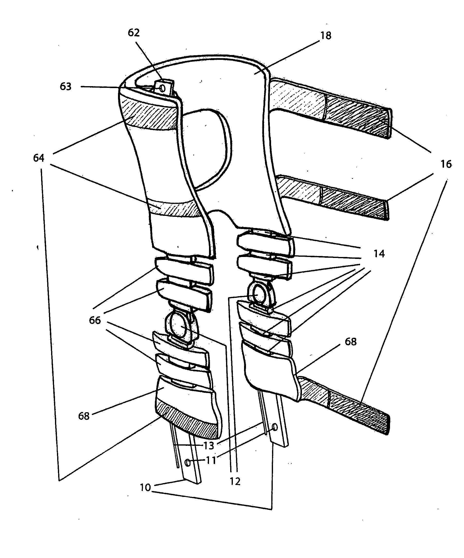
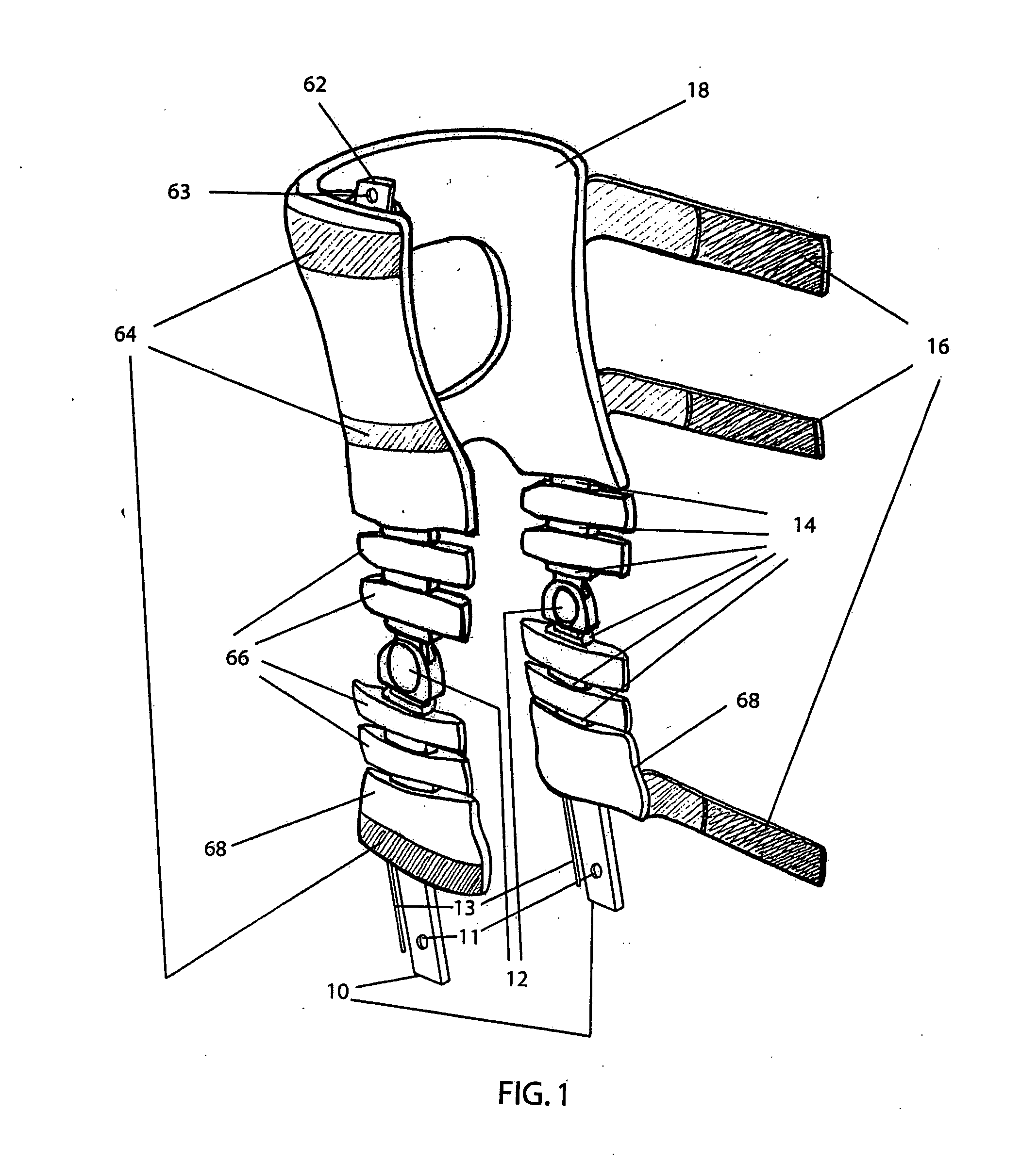
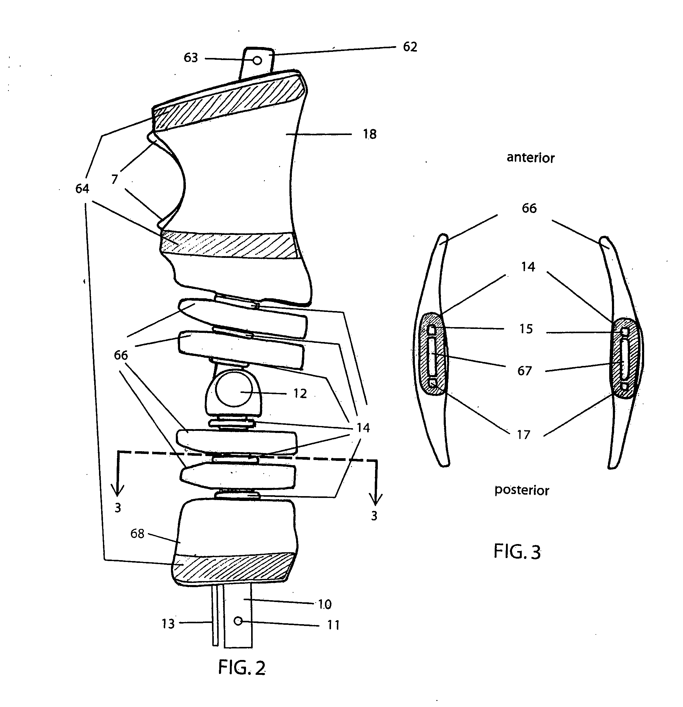
[0083] Many patients with severe calf and thigh weakness would use a configuration comprising of a posterior strut AFO connected to the knee orthosis. The knee orthosis strut 67 would be oriented 5 degrees forward of the line between the wearer's anatomical knee joint and hip joint, and 5 degrees forward of the line between the anatomical knee and ankle joints. This would make the knee moment equal to zero at a knee flexion angle of 10 degrees. There would be a knee extension assist consisting of elastic material. The knee joints 12 would be locking / unlocking knee joints with a lock / unlock rod 48,13 attached to the foot shell 46 of a posterior strut AFO connected through a pivot 54. The orthosis knee joint ...


PUM


Abstract

A knee orthosis comprising of at least one deflection limiter (66) separated by gaps (10) on one or more struts (67), which are attached to a thigh shell (18) and a calf shell (68). The stiffness of the brace can easily be controlled in sagittal, transverse, and coronal planes whereby a person may obtain improved gait.

Description

CROSS-REFERENCE TO RELATED APPLICATION [0001] This application claims the benefit of U.S. Provisional Application No. 60 / 663556 filed Mar. 18, 2005.STATEMENT REGARDING FEDERALLY SPONSORED RESEARCH [0002] The U.S. Government has a paid-up license in this invention and the right in limited circumstances to require the patent owner to license others on reasonable terms as provided for by the terms of Grant No. H133E003001 awarded by the U.S. Department of Education.SEQUENCE LISTING OR PROGRAM [0003] Not applicable BACKGROUND—FIELD OF THE INVENTION [0004] The present invention relates to improvements in a knee orthosis (KO) used for supporting a person's knee along with extensions for supporting the user's hip and ankle. The orthosis of the present invention assists the user in extension and flexion of the user's hip, knee, and ankle while controlling sagittal, transverse, and / or coronal plane stiffnesses and deflections. BACKGROUND—DISCUSSION OF PRIOR ART [0005] Knee Orthoses are curre...

Claims


Application Information

Patent Timeline
IPC IPC(8): A61F5/00
CPCA61F5/0102A61F5/0125A61F5/0127A61F2005/0165
Inventor REYNOLDS, RONANWEBER, ROGERLANDSBERGER, SAMUEL
Owner REYNOLDS RONAN
Why Eureka
Try Eureka