
Low Thermal Stress Engineered Metal Structures

a technology of engineered metal and low thermal stress, applied in metal-working apparatus, transportation and packaging, coatings, etc., can solve the problems of severe design constraints, large temperature changes of many structures of technological importance, and severe thermal stress of heat exchangers that undergo non-continuous use, so as to reduce overall system temperatures and/or control thermal stress. , the effect of dissipating thermal energy

Active Publication Date: 2020-10-22
POWDERMET
View PDF0 Cites 9 Cited by
  • Summary
  • Abstract
  • Description
  • Claims
  • Application Information

AI Technical Summary

Benefits of technology

The patent is about designing structures that are subjected to thermal or other strain-induced loads. It describes a new type of composite material with high thermal conductivity and controlled stiffness that can help reduce thermal stresses in these structures. This material is useful for a variety of applications such as heat shields, cryotanks, engine ducts, and aeroshells. Overall, this patent provides a solution for protecting thermal structures from repetitive thermal loads while maintaining their performance.

Problems solved by technology

Numerous structures with technological importance are subjected to large temperature changes during use.
These large temperature swings or gradients in such applications which occur on start-up, operation, or use, impose severe design constraints in addition to environmental concerns such as corrosion or oxidation.
Heat exchangers—Heat exchangers that undergo non-continuous use experience severe thermal stresses.
Such heat exchangers can have large temperature drops during the life of their use, which large temperature drops can cause thermal fatigue.
Materials used to form these heat exchangers require high thermal conductivity, but also low CTE and low stiffness to minimize thermal stresses.
These structures need high thermal conductivity but suffer from high thermal gradients during transient and steady state use conditions.
Active cooling is costly, normally requires bulky materials and, because it has many moving parts and fluids, is subject to reliability and maintenance issues.

Method used


Image

  • Low Thermal Stress Engineered Metal Structures
  • Low Thermal Stress Engineered Metal Structures
  • Low Thermal Stress Engineered Metal Structures

Examples


example 1

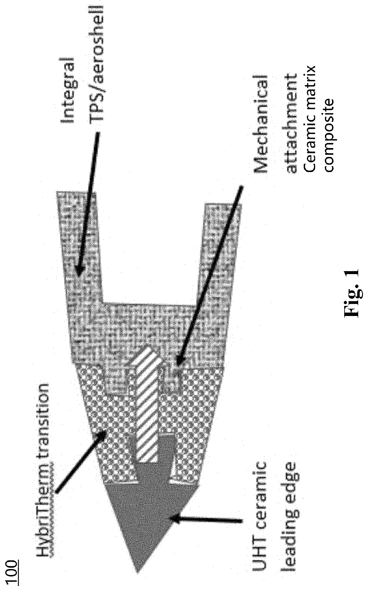
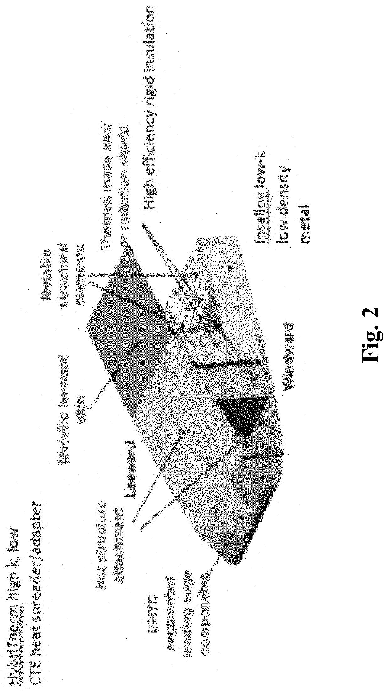
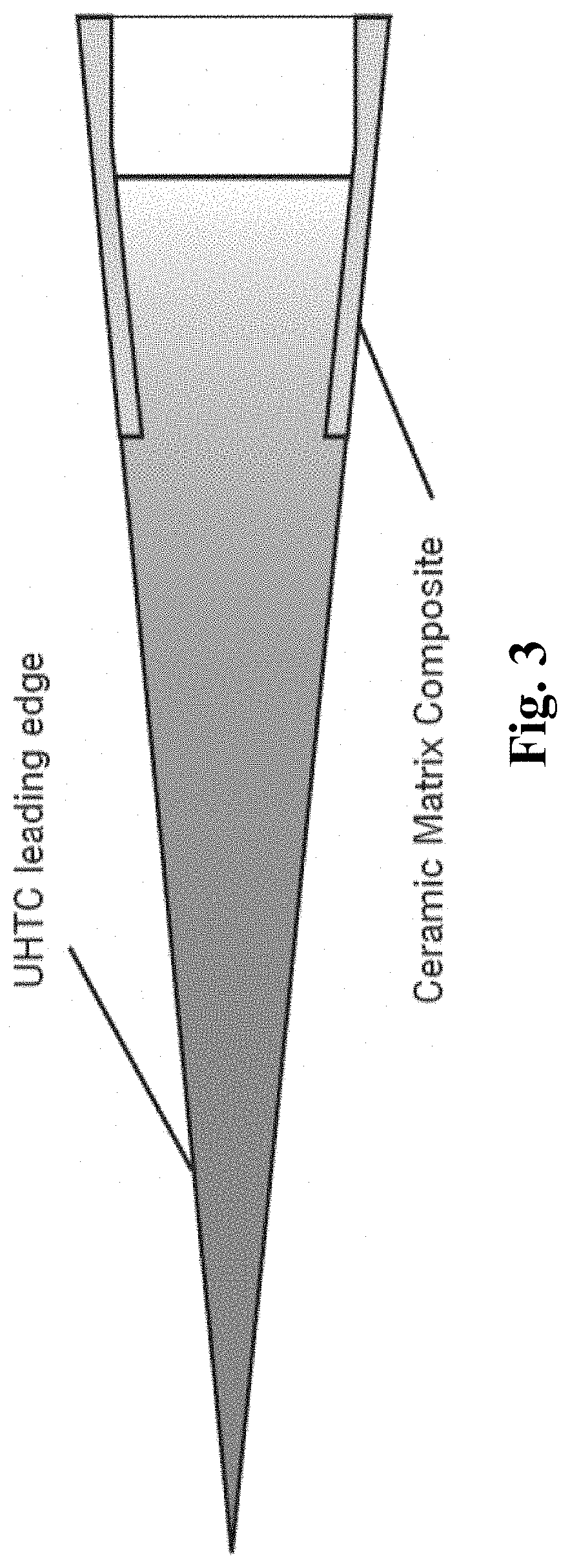
[0241]A high speed vehicle airframe panel was designed using a ceramic leading edge insert and an insulating structure. A thermal transition piece is fabricated from a BN-filled FeCrAlY, in the structure illustrated in FIG. 1 or 2 or 3. The HybriTherm thermally-engineered attachment structure includes a MA956 alloy (37-57 wt. % iron, 16-23 wt. % chromium, 2-7 wt. % aluminum, 0-1 wt. % titanium, 0-1 wt. % copper, 0-1 wt. % manganese, 0-1 wt. % cobalt, 0-1 wt. % nickel, 0-1 wt. % Y2O3, <0.2 wt. % carbon) multi-phase composite that is fabricated by premixing 40 vol. % of 60 micron D50 spheroidized BN fillers (boron nitride), which possess a 80-92 wt. % increase (and all values and ranges therebetween) addition of nickel coating by a solution based adsorption method, with 15-35 vol. % (and all values and ranges therebetween) (e.g., 25 vol. %) of 1-10 micron powder (and all values and ranges therebetween) mixture of 70-80 wt. % iron (and all values and ranges therebetween) (e.g., 75.5 wt...

example 2

[0242]A multi-phase composite panel was fabricated using powder metallurgy processing from Hastelloy-N (e.g., 68-73 wt. % nickel, 5-8 wt. % chromium, 14-18 wt. % molybdenum, <0.2 wt. % carbon, <0.5 wt. % cobalt, <0.5 wt. % copper, 0-1 wt. % tungsten, <0.6 wt. % aluminum, <0.6 wt. % titanium) and alloy powders using the sequence described in Example 1, but sintered at 950-1200° C. (and all values and ranges therebetween) (e.g., 1080° C.). The material was fabricated into thin sheets, which were alternately etched with complex channels. The solid panels and machined panels were stacked and spark plasma bonded into a solid core of a heat exchanger. The material demonstrates a 400-500% increase (and all values and ranges therebetween) in thermal conductivity compared to its parent metal, Hastelloy-N. Additional property modifications include a 65-90% reduction (and all values and ranges therebetween) reduction in modulus, a 5-15% reduction (and all values and ranges therebetween) in ...

example 3

[0243]A magnesium multi-phase composite electronic box was fabricated by melt infiltrating a calcium-modified AZ61 alloy containing calcium and cerium (85-92 wt. % magnesium, 5.80-7.2 wt. % aluminum, 0.4-1.5 wt. % zinc, up to 0.15 wt. % manganese, up to 0.1 wt. % silicon, up to 0.05 wt. % copper, up to 0.005 wt. % nickel, up to 0.005 wt. % iron, up to 2 wt. % calcium, up to 1 wt. % cerium, up to 1.5 wt. % graphene platelets) into a 35-50 vol. % (and all values and ranges therebetween) (e.g., 40 vol. %) spheroidized BN filler preform space using prealloyed AZ61 (88-92 wt. % magnesium, 5.80-7.2 wt. % aluminum, 0.4-1.5 wt. % zinc, up to 0.15 wt. % manganese, up to 0.1 wt. % silicon, up to 0.05 wt. % copper, up to 0.005 wt. % nickel, up to 0.005 wt. % iron)+titanium powders applied (blended) to the fillers using squeeze casting. The 2″ thick billets were extruded into a complex finned profile for use as heat sinks in electronic boxes.


PUM

PropertyMeasurementUnit
Temperatureaaaaaaaaaa
Fractionaaaaaaaaaa

Abstract

A structured multi-phase composite which include a metal phase, and a low stiffness, high thermal conductivity phase or encapsulated phase change material, that are arranged to create a composite having high thermal conductivity, having reduced / controlled stiffness, and a low CTE to reduce thermal stresses in the composite when exposed to cyclic thermal loads. The structured multi-phase composite is useful for use in structures such as, but not limited to, high speed engine ducts, exhaust-impinged structures, heat exchangers, electrical boxes, heat sinks, and heat spreaders.

Description

[0001]The present disclosure claims priority on U.S. Provisional Patent Application Ser. No. 62 / 866,927 filed Jun. 25, 2020, which is incorporated herein by reference.[0002]The present disclosure is a continuation-in-part of U.S. Ser. No. 16 / 110,600 filed Aug. 23, 2018, which in turn claims priority on U.S. Provisional Patent Application Ser. No. 62 / 549,704 filed Aug. 24, 2017, which is incorporated herein by reference.[0003]This application is also a continuation-in-part of U.S. Ser. No. 16 / 110,600 filed Aug. 23, 2018, which in turn a continuation-in-part of U.S. Ser. No. 14 / 752,166 filed Jun. 26, 2015 now U.S. Pat. No. 10,092,954; issued Oct. 9, 2018), which in turn claims priority on U.S. Ser. No. 13 / 445,810 filed Apr. 12, 2012 (now U.S. Pat. No. 9,096,034; issued Aug. 4, 2015), which in turn claims the benefit of U.S. Provisional Application Ser. No. 61 / 474,712 filed Apr. 12, 2011.REGARDING FEDERALLY SPONSORED RESEARCH OR DEVELOPMENT STATEMENT[0004]Portions of this invention wer...

Claims


Application Information

Patent Timeline
IPC IPC(8): B22F3/11B32B5/18B21D31/00C22C32/00C22C49/00C22C49/11C22C49/06B32B5/16B32B5/20B22F3/16C22C1/10B22F1/05B22F1/17
CPCC22C49/00C22C49/11B22F2003/1106B32B5/20C22C1/1084B21D31/00C22C32/0078C22C32/0036C22C49/06B22F3/16B32B5/16B22F2998/10B32B5/18C22C32/0031B22F3/1112C22C2026/002C22C2026/003B22F2009/041B22F3/105B22F2003/1051B22F3/1021B22F3/04B22F2009/042C22C1/0433C22C33/02B22F2003/247B22F3/20C22C49/14C04B37/02C04B2237/32C04B2237/38C04B2237/40C04B2237/58C04B2237/84B32B18/00B22F1/05B22F1/17C22C29/14
Inventor SHERMAN, ANDREW
Owner POWDERMET
Learn More