Subgasket Design to Dissipate Thermal Energy Generated from Catalytic Combustion Experienced in a PEM Fuel Cell

Active Publication Date: 2014-04-10
GM GLOBAL TECH OPERATIONS LLC
View PDF5 Cites 0 Cited by
  • Summary
  • Abstract
  • Description
  • Claims
  • Application Information

AI Technical Summary

Benefits of technology

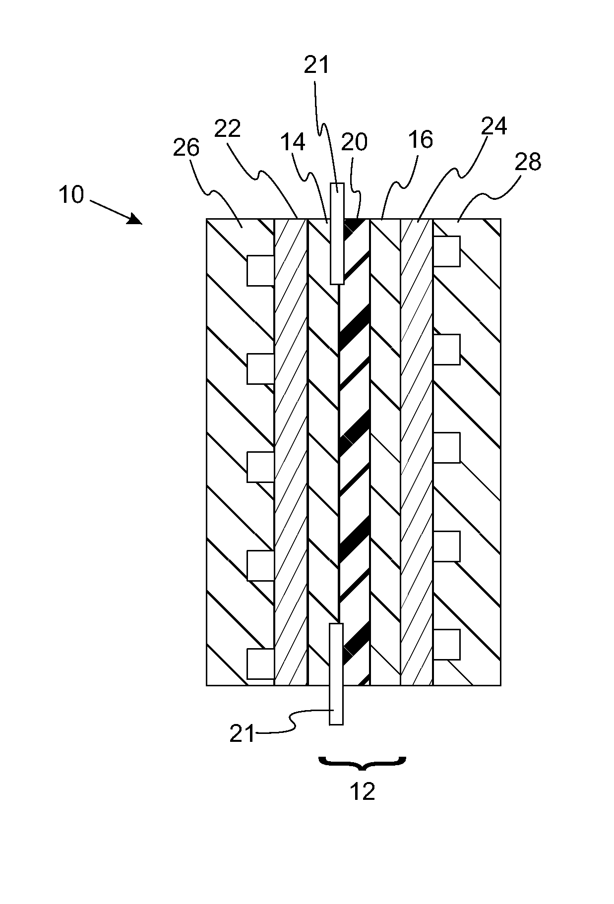
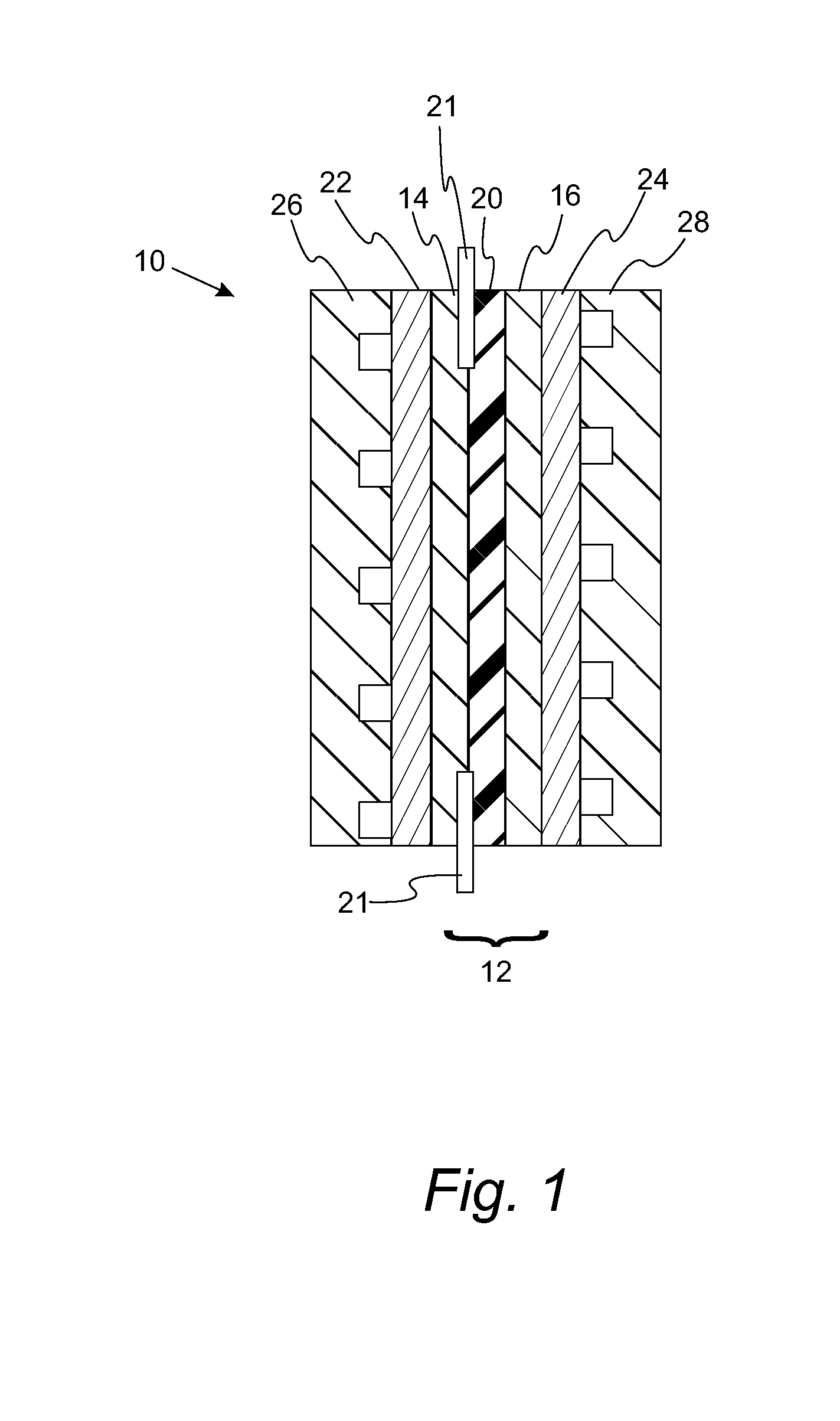
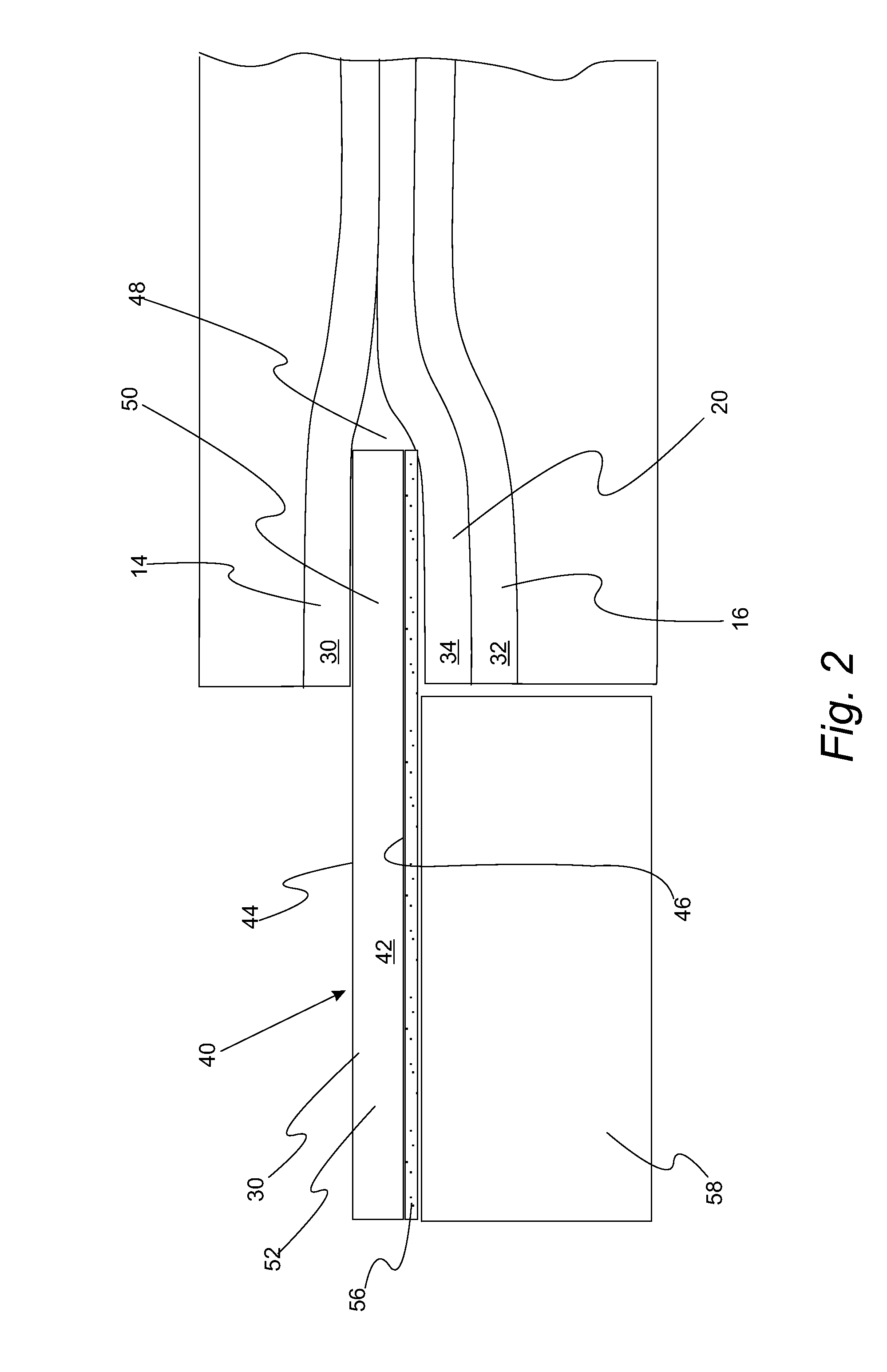
[0005]The present invention solves one or more problems of the prior art by providing in at least one embodiment a fuel cell component for dissipating heat. The fuel cell component includes a sub-gasket including a structural component and a thermally conductive layer. The sub-gasket defines a central opening while the structural component includes a first side and a second side. The sub-gasket also has an inner portion proximate to the central opening and an outer portion. The inner portion is positioned between the cathode layer outer edge and the

Problems solved by technology

Although the prior art subgasket designs work reasonably well during normal operation, these partic

Method used


Image

  • Subgasket Design to Dissipate Thermal Energy Generated from Catalytic Combustion Experienced in a PEM Fuel Cell
  • Subgasket Design to Dissipate Thermal Energy Generated from Catalytic Combustion Experienced in a PEM Fuel Cell
  • Subgasket Design to Dissipate Thermal Energy Generated from Catalytic Combustion Experienced in a PEM Fuel Cell

Examples


Embodiment Construction

[0016]Reference will now be made in detail to presently preferred compositions, embodiments and methods of the present invention, which constitute the best modes of practicing the invention presently known to the inventors. The Figures are not necessarily to scale. However, it is to be understood that the disclosed embodiments are merely exemplary of the invention that may be embodied in various and alternative forms. Therefore, specific details disclosed herein are not to be interpreted as limiting, but merely as a representative basis for any aspect of the invention and / or as a representative basis for teaching one skilled in the art to variously employ the present invention.

[0017]Except in the examples, or where otherwise expressly indicated, all numerical quantities in this description indicating amounts of material or conditions of reaction and / or use are to be understood as modified by the word “about” in describing the broadest scope of the invention. Practice within the nume...


PUM


Abstract

A fuel cell component includes a sub-gasket including a structural component and a thermally conductive layer. The sub-gasket defines a central opening while the structural component includes a first side and a second side. The sub-gasket also has an inner portion proximate to the central opening and an outer portion. The inner portion is positioned between the cathode layer outer edge and the ion-conducting membrane outer edge or between the anode layer outer edge and the ion-conducting membrane outer edge. Finally, the thermally conductive layer contacts the second side of the structural component. Advantageously, the thermally conductive layer dissipates locally generated heat caused by unintended particles falling on the sub-gasket.

Description

BACKGROUND OF THE INVENTION[0001]Fuel cells are used as an electrical power source in many applications. In particular, fuel cells are proposed for use in automobiles to replace internal combustion engines. A commonly used fuel cell design uses a solid polymer electrolyte (“SPE”) membrane or proton exchange membrane (“PEM”), to provide ion transport between the anode and cathode.[0002]In proton exchange membrane type fuel cells, hydrogen is supplied to the anode as fuel, and oxygen is supplied to the cathode as the oxidant. The oxygen can either be in pure form (O2) or air (a mixture of O2 and N2). PEM fuel cells typically have a membrane electrode assembly (“MEA”) in which a solid polymer membrane (i.e., ion conducting membrane) has an anode catalyst on one face, and a cathode catalyst on the opposite face. The anode and cathode layers of a typical PEM fuel cell are formed of porous conductive materials, such as woven graphite, graphitized sheets, or carbon paper to enable the fuel...

Claims


Application Information

Patent Timeline
IPC IPC(8): H01M8/02H01M8/10
CPCH01M8/0297H01M8/04074H01M8/0273H01M8/04067H01M2008/1095Y02E60/50
Inventor BEUTEL, MATTHEW J.TOWNER, CHRISTOPHER J.FAGLEY, JOHN C.
Owner GM GLOBAL TECH OPERATIONS LLC
Why Eureka
Try Eureka