Hot dry rock generation system

a technology of hot dry rock and generation system, which is applied in the direction of mechanical power devices, mechanical equipment, mechanical devices, etc., can solve the problems of large white smoke generation, crack formation in hot dry rock, and operators who work in the neighborhood of the collecting tank b>4/b> being exposed to danger, so as to save energy

Inactive Publication Date: 2014-03-04
MITSUBISHI HITACHIPOWER SYST LTD
View PDF24 Cites 0 Cited by
  • Summary
  • Abstract
  • Description
  • Claims
  • Application Information

AI Technical Summary

Benefits of technology

[0011]In view of the inconveniences or difficulties of the conventional technology, the present invention aims at providing a hot dry rock generation system in which the temperature of the heat carrier can be appropriately regulated, and the thermal energy can be utilized so as to save energy.
[0013]According to the above-described disclosure, a heat exchanger is provided so that the heat carrier streaming out of the production well is charged into the heat exchanger; thus, the temperature of the heat carrier can be further increased at the heat exchanger, or the thermal energy of the heat carrier can be absorbed at the heat exchanger so as to supply the absorbed thermal energy to a heat consumption plant. Accordingly, the temperature of the heat carrier can be appropriately regulated, and the thermal energy can be utilized so as to save energy.
[0014]A preferable embodiment of the present invention is the hot dry rock generation system, wherein the heat exchanger is arranged between the power generation plant and the collecting tank, the hot dry rock generation system further comprising a heat consumption plant that consumes the thermal energy supplied from the heat exchanger. According to the above-described disclosure, in a case where the temperature of the heat carrier discharged from the power generation plant is still high, the thermal energy can be supplied to a heat consumption plant such as warm pool facilities, via the heat exchanger, without making the thermal energy dissipate outward. In other words, in a case where the temperature of the heat carrier discharged from the power generation plant utilizing the primary part of the thermal energy of the heat carrier is still higher than the ambient temperature, the heat consuming plant can utilize the secondary part of the thermal energy of the heat carrier; in this way, the thermal energy can be effectively utilized in and over two stages. Further, the temperature of the heat carrier discharged into the collecting tank can be decreased to a level near to the ambient temperature; thus, white smoke generation in the neighborhood of the collecting tank can be evaded. Moreover, the operators who work in the neighborhood of the collecting tank can be free from the danger of burns. In addition, potential countermeasures against the high temperature regarding the sealing water pump feeding the water back to the hot dry rock can be dispensed with. Another preferable embodiment is the hot dry rock generation system, wherein the heat exchanger is arranged between the production well and the power generation plant, the hot dry rock generation system further comprising a heat supply plant that supplies the thermal energy to the heat exchanger.
[0017]According to the above-described disclosure, the temperatures and the pressures of the heat carrier that is discharged from the production well and streams toward power generation plant can be measured. Based on the measured temperatures and pressures, the delivery head and the opening level of the sealing water pump are determined so that the flow rate and the pressure of the heat carrier discharged from the production well are regulated. Hence, the flow rate and the pressure of the heat carrier discharged from the production well can be stabilized; further, the controller receives load setting signals from the power generation plant so that the hot dry rock generation system can be operated while keeping the optimal hot-water flow rate in response to the power output of the generator.
[0019]According to the above-described disclosure, the pressure of the heat carrier before the recharge well is also measured; thus, the heat carrier pressure loss between the inlet of the recharge well and the outlet of the production well can be measured so that the change of the state of the hot dry rock can be detected. Further, control correction according to feedforward control approach is performed so that the pressure on the production well side is stabilized.

Problems solved by technology

Further, after the chutes are formed, the excavation is performed further deeply, by additional several meters from the bottom of the chutes; and, high pressure water is sent to the hot dry rock through the steel pipes so that high water pressure works on the bedrock of the hot dry rock, and cracks are formed in the hot dry rock.
In the conventional hot dry rock generation system, however, when the hot-water which temperature exceeds 100° C. is discharged toward or into the collecting tank 4, the hot-water is once set free toward the open air; due to the relieved energy, a vast amount of white smoke is generated so as to defile the landscape of the site.
Further, since the water in the collecting tank 4 is placed under a boiling condition, the operators who work in the neighborhood of the collecting tank 4 are exposed to danger.

Method used


Image

  • Hot dry rock generation system
  • Hot dry rock generation system
  • Hot dry rock generation system

Examples


first embodiment

(First Embodiment)

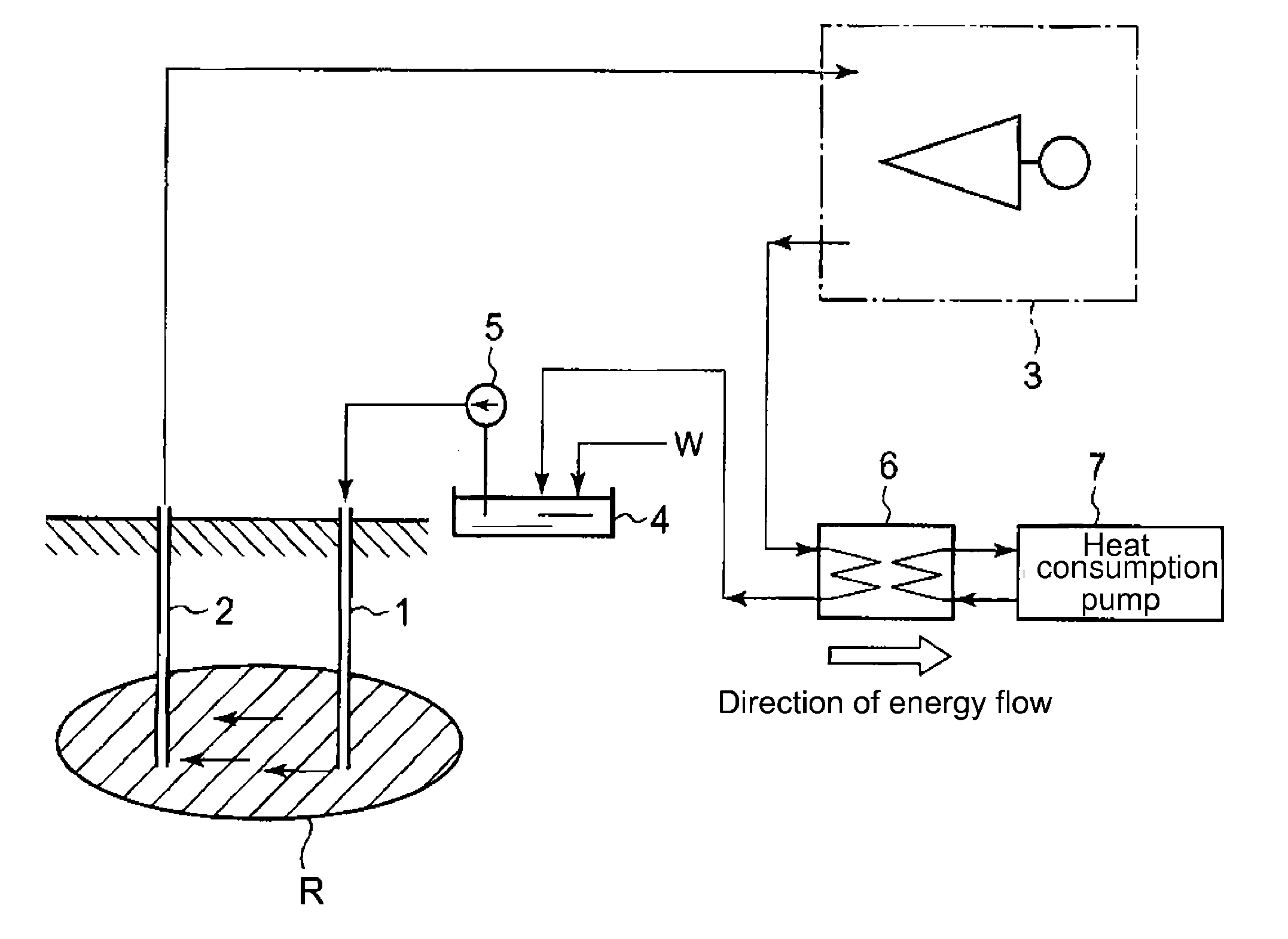
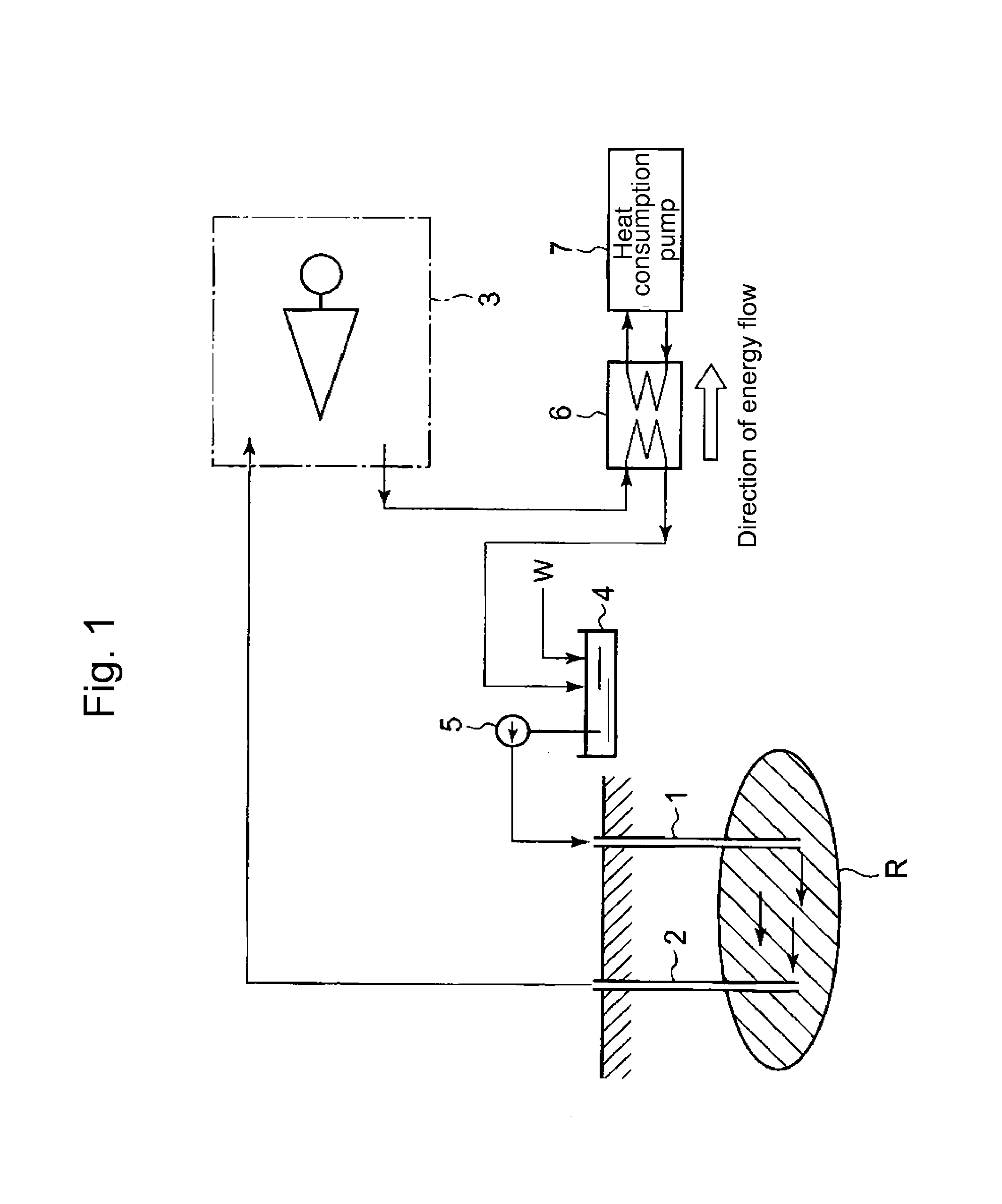
[0031]FIG. 1 shows a first embodiment regarding hot dry rock power generation system according to the present invention. The hot dry rock power generation system according to this embodiment has a recharge well 1 and a production well 2, each well being formed from the ground to an underground hot dry rock R. The hot dry rock power generation system may have a plurality of recharge wells 1 and production wells 2. Through the recharge well 1, water as a heat carrier is supplied to the hot dry rock R; the water reaching the hot dry rock R passes through the cracks in the hot dry rock R, the cracks being formed in advance by breaking the hot dry rock R into pieces by means of water pressure. Hereby, the heat carrier means a general term for fluid that carries heat. Besides fresh water, seawater that exists on the ground surface can be used as a heat carrier. The present invention has no special selection regarding the kind of the heat carrier.

[0032]Further, in passing...

second embodiment

(Second Embodiment)

[0050]FIG. 6 shows a second embodiment regarding hot dry rock power generation system according to the present invention. Incidentally, the same components in the second embodiment as in the first embodiment are given common numerals; and, explanation repetitions are omitted.

[0051]The second embodiment differs from the first embodiment in that the arrangement of the heat exchanger is different; and, the heat exchanger 6 is connected to the heat consumption plant 7 in the first embodiment, while the heat exchanger 6 is connected to the heat supply plant 8 in the second embodiment. The heat exchanger 6 in this second embodiment is placed between the production well 2 and the power generation plant 3.

[0052]The heat supply plant 8 supplies thermal energy to the heat carrier in the hot dry rock generation system, via the heat exchanger 6. Thus, when the increase of the power output of the power generation plant 3 is required, the power increase can be realized by use o...

third embodiment

(Third Embodiment)

[0057]FIG. 7 shows a third embodiment regarding hot dry rock power generation system according to the present invention. Incidentally, the same components in the third embodiment as in the first and second embodiments are given common numerals; and, explanation repetitions regarding the same components are omitted.

[0058]The third embodiment differs from the second embodiment in that the hot dry rock generation system is provided with an additional system that stabilizes the temperature and the pressure of the heat carrier discharged from the production well. The hot dry rock generation system according to this embodiment is provided with:[0059]an RPM control unit (a rotation speed control unit) 5a that controls the delivery head of the sealing water pump 5; and[0060]a flow regulating valve 12 that is arranged between the sealing water pump 5 and the recharge well.[0061]Incidentally, the flow regulating valve 12 may be arranged between the production well 2 and the ...


PUM


Abstract

A hot dry rock generation system, having: a recharge well that is formed from the ground to an underground hot dry rock into which a heat carrier streams through the recharge well; a production well that is formed from the underground hot dry rock from which the heated heat carrier is streams through the production well; a power generation plant that converts the thermal energy of the heat carrier streaming out of, into electric energy; a collecting tank that stores the heat carrier discharged from the power generation plant; a sealing water pump that sucks the heat carrier collected in the collecting tank and makes the heat carrier stream into the recharge well, whereby the hot dry rock generation system is provided with a heat exchanger into which the heat carrier streaming out of the production well streams.

Description

BACKGROUND OF THE INVENTION[0001]1. Field of the Invention[0002]The present invention relates to a hot dry rock generation system in which a heat carrier is made stream into the high temperature hot dry rock existing underground; the heat carrier heated by the hot dry rock is collected; and, power generation is performed by use of the heated heat carrier.[0003]It is hereby noted that the term “invention” or “present invention” in this specification means the aspect, the mode or the embodiment disclosed by this specification.[0004]2. Background of the Invention[0005]The hot dry rock generation system is conventionally known to the public (e.g. Patent References JP 1978-246403, JP1992-234576 and JP1999-223176); in the conventional hot dry rock generation system, a heat carrier is made stream into the high temperature hot dry rock deeply situated beneath the ground surface (e.g. at the depth of the 2000 to 4000 m). Hereby, the hot dry rock means high temperature rock existing undergrou...

Claims


Application Information

Patent Timeline
Patent Type & Authority Patents(United States)
IPC IPC(8): F03G7/00
CPCF03G7/04
Inventor NAKAMURA, TAKASHIHIRAMOTO, KOJINAKAJO, ICHIROYOKOHAMA, YOSHIYUKI
Owner MITSUBISHI HITACHIPOWER SYST LTD
Why Eureka
Try Eureka