Heat-sinking apparatus for light pipe

a technology of heat sinking apparatus and light pipe, which is applied in the direction of printing, instruments, etc., can solve the problems of reducing the luminous efficiency of the reflective the size and weight of the transmission-type liquid crystal display panel cannot be reduced, and the large size of the crt projector generally has a large size and relative low resolution, so as to prevent the breakdown of the light pipe and dissipate the thermal energy. the a light pipe heat-sinking apparatus of heat-sinking apparatus of heat-sinking apparatus of light pipe heat-sinking apparatus of light pipe heat-sinking apparatus and light-pipe heat-sinking apparatus and light-pipe heat-sinking apparatus and light-pipe heat-sead pipe-type liquid-type heat-sead pipe-type technology, which is applied in lighting and heating apparatus, which is applied in lighting and heating equipment, and achieves the effect of pipe-type heat-si-pipe-typ

Inactive Publication Date: 2005-01-04
BENQ CORP
View PDF6 Cites 3 Cited by
  • Summary
  • Abstract
  • Description
  • Claims
  • Application Information

AI Technical Summary

Benefits of technology

It is therefore an aspect of the present invention to provide a simple heat-sinking apparatus for a light pipe to uniformly distribute thermal energy generated by the light source over the light pipe, and further to dissipate the thermal energy distributed over the light pipe.
The present invention provides a heat-sinking apparatus for a light pipe to prevent the breakdown of the light pipe. The heat-sinking apparatus for the light pipe of the present invention includes a cover made of heat conductive material. By covering the light pipe with the cover, thermal energy generated by the light source is uniformly distributed over the light pipe.
It is another aspect of the present invention to provide a heat-sinking apparatus made of commercial materials, such as a metal sheet of excellent heat conduction ability, which simplifies the production process. In a preferred embodiment of the present invention, the cover is made of aluminum foil.
It is a further aspect of the present invention to provide a heat-sinking apparatus, which further includes a fan for dissipating the thermal energy distributed over the light pipe and effectively dissipates thermal energy to prevent the breakdown of a light pipe.

Problems solved by technology

However, CRT projectors generally have dimensions of large size and have relative low resolution, and therefore have been gradually replaced by liquid crystal display (LCD) projectors in recent years.
However, a transmission-type liquid crystal display panel is restricted by the light transmission ratio, which lowers the luminous efficiency compared with a reflective-type liquid crystal display panel.
Besides, the size and the weight of the transmission-type liquid crystal display panel cannot be reduced due to the structure limitation of the optical engine.

Method used


Image

  • Heat-sinking apparatus for light pipe
  • Heat-sinking apparatus for light pipe
  • Heat-sinking apparatus for light pipe

Examples


Embodiment Construction

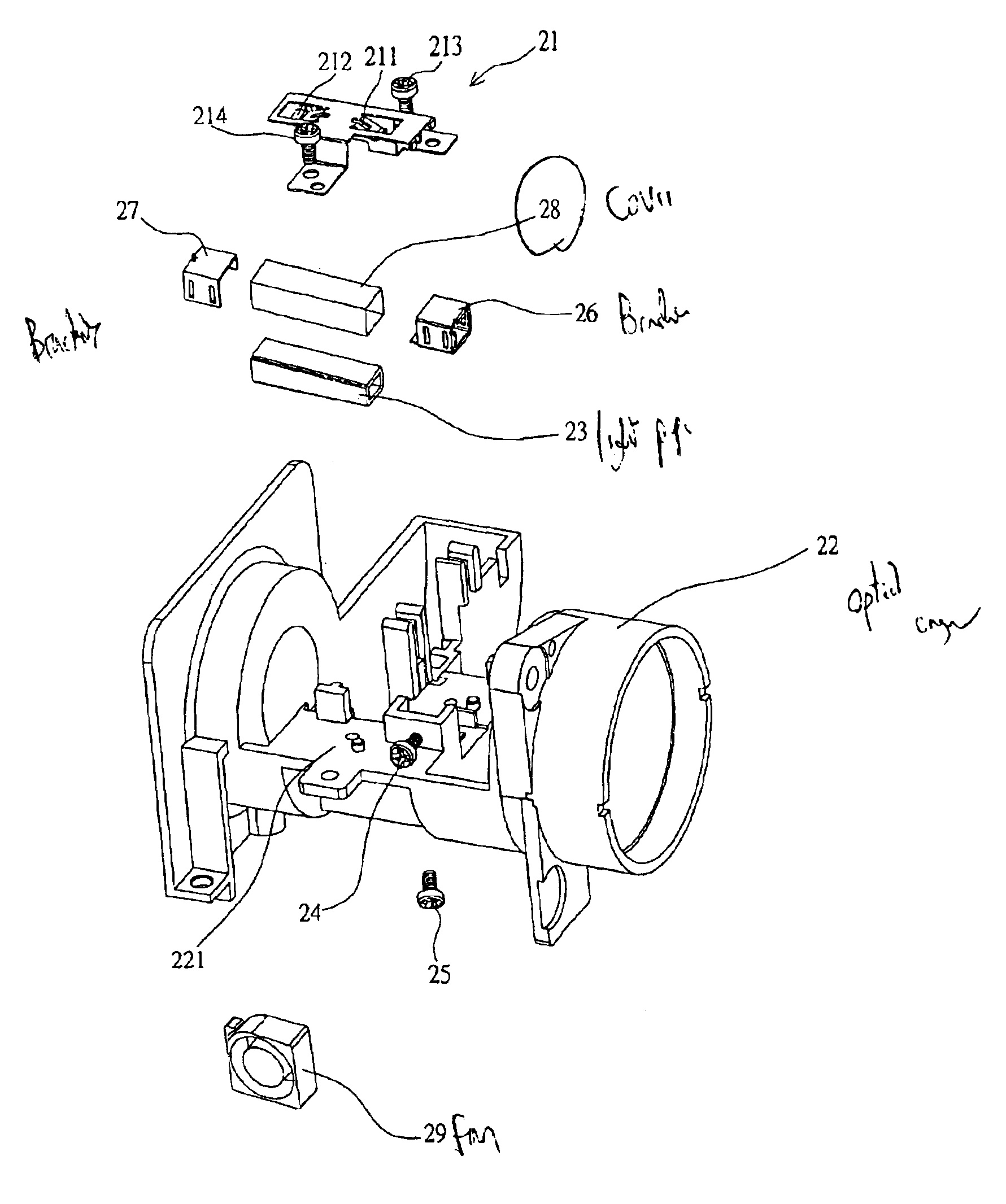
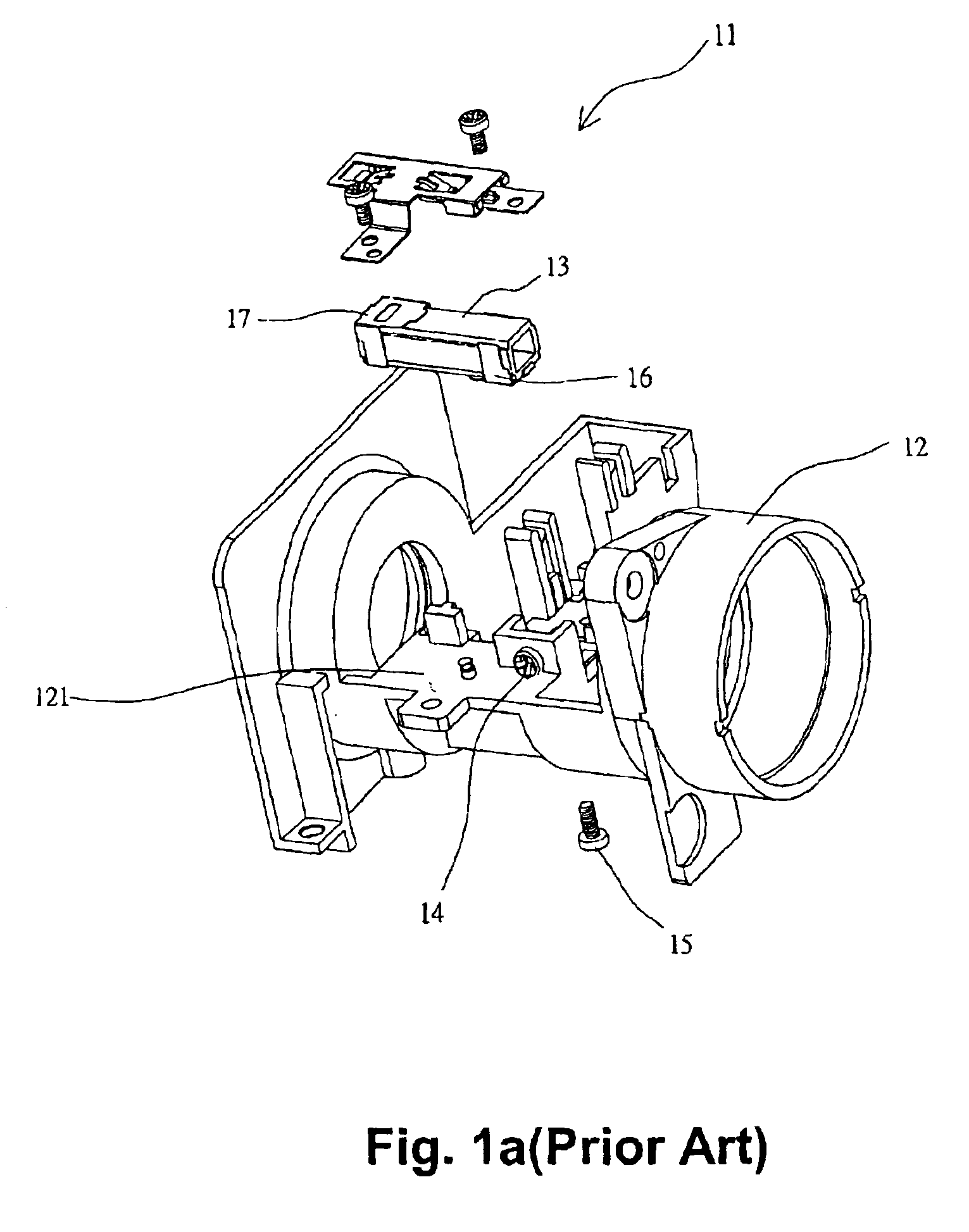
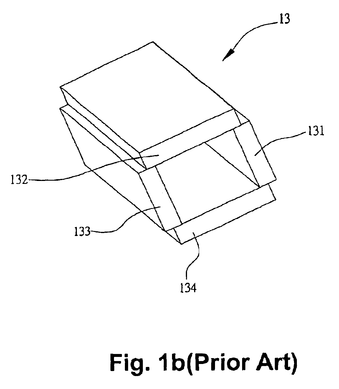
A light pipe is an important optical refractive element in a digital liquid processing projector. Generally, the light pipe is disposed on a base surface of an optical engine, and optically couples with a light source. The incident light from the light source is refracted by the internal surface of the light pipe, then through a trichromatic rotation wheel of the optical engine, to a digital micromirror device (DMD) chip, which reflects the light to form an image on a screen. Four pieces of glass are typically constructed together using adhesive to form the light pipe. Therefore, when the temperature of the light pipe is over the heat resistance of the adhesive, the light pipe is likely to breakdown. The present invention provides a heat-sinking apparatus for the light pipe, which eliminates the disadvantages of the prior art, and further prevents Blue Edge phenomenon induced by the breakdown of the light pipe.

Referring to FIG. 2a and FIG. 2b, a light pipe 23 is positioned on surfac...


PUM


Abstract

The present invention provides a heat-sinking apparatus for a light pipe. The light pipe is disposed on an optical engine of a projector and optically couples with a light source. The heat-sinking apparatus includes a cover made of a heat conductive material and a fan. The cover covers the light pipe and uniformly distributes thermal energy generated by the light source over the light pipe. The fan dissipates the thermal energy distributed over the light pipe.

Description

CROSS REFERENCE TO RELATED APPLICATIONSThis application claims priority to Taiwan Patent Application No. 090129127 entitled “Heat-sinking Apparatus for Light Pipe”, filed Nov. 23, 2001.FIELD OF INVENTIONThe present invention generally relates to a heat-sinking apparatus for a light pipe and, more particularly, to a heat-sinking apparatus for a light pipe used in a Digital Light Processing (DLP) projector.BACKGROUND OF THE INVENTIONA cathode-ray tube (CRT) has typically been used in projection technology in the past. However, CRT projectors generally have dimensions of large size and have relative low resolution, and therefore have been gradually replaced by liquid crystal display (LCD) projectors in recent years.The liquid crystal display technology involves transmitting incident light from a light source through a trichromatic filter, then projecting three primary colors (Red, Green, Blue) to three liquid crystal display panels (LCD panels), and integrating these three primary colo...

Claims


Application Information

Patent Timeline
Patent Type & Authority Patents(United States)
IPC IPC(8): H05K7/20
CPCH05K7/20
Inventor CHANG, HUNGWONG, LI-KUAN
Owner BENQ CORP
Why Eureka
Try Eureka