
Information processing system, pipeline processor, and computer readable recording medium in which busy judgment program is stored

a technology of information processing system and recording medium, which is applied in the field of information processing system and pipeline processor in which the busy judgment program is stored, can solve the problem of not being able to effectively utilize the number of entries, and achieve the effect of not increasing hardware resources

Inactive Publication Date: 2006-09-21
FUJITSU LTD
View PDF12 Cites 5 Cited by
  • Summary
  • Abstract
  • Description
  • Claims
  • Application Information

AI Technical Summary

Benefits of technology

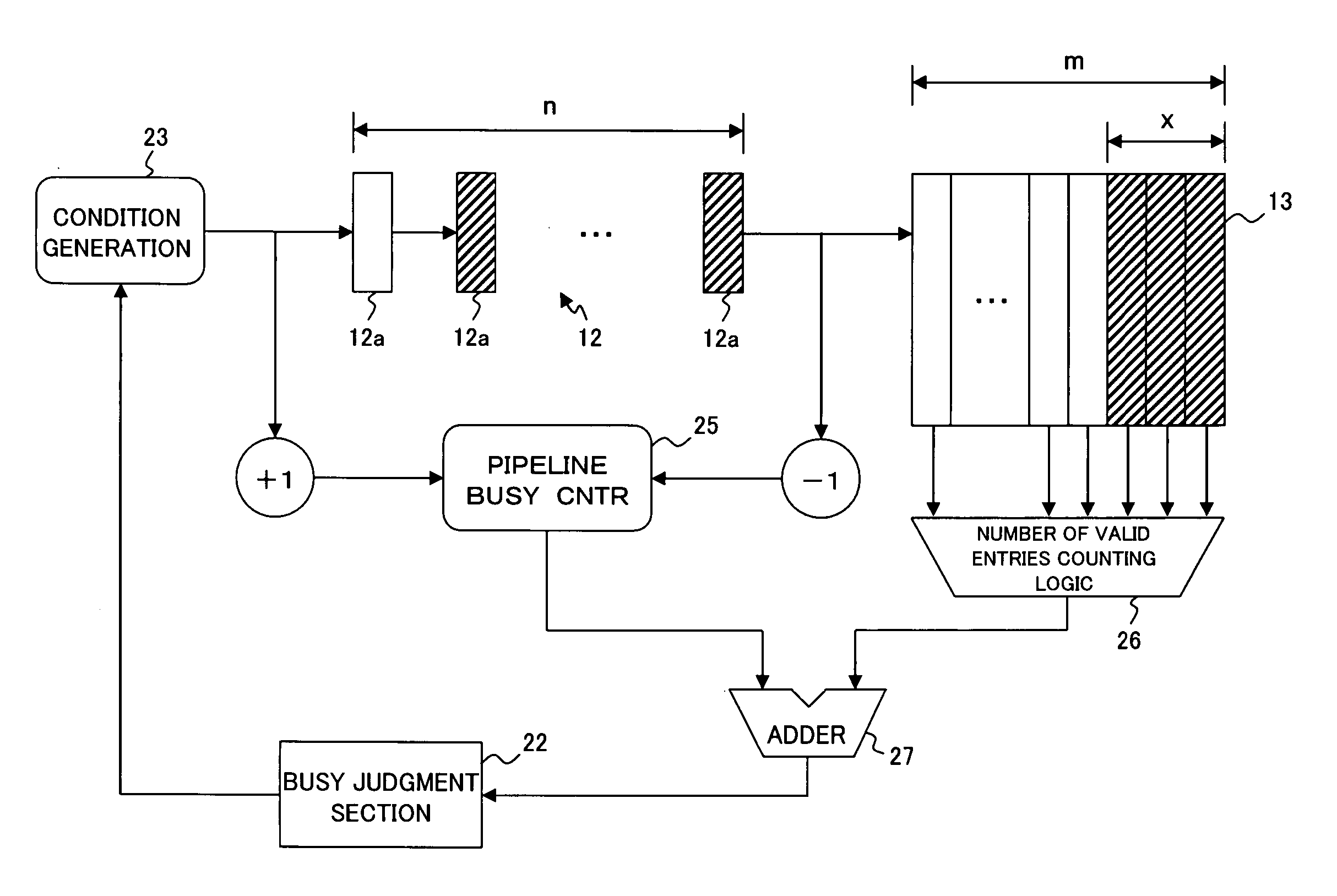
The present invention aims to make a system that can make a busy judgment of a register without increasing hardware resources. The system includes a controller that notifies multiple pipeline processors of a request and determines the final operation for the request. The pipeline processor includes a pipeline register and a request queue for storing and retaining the request. A judgment section determines if the request is valid or not. A first counter counts the number of valid requests in the registers. A busy judgment section determines if the request queue is in a busy state based on the number of valid requests. A judgment result notification section notifies the controller of the result of the busy judgment section. The system allows for efficient and effective processing of requests in an information processing system.

Problems solved by technology

However, the busy judgment method by the LCST generation logic 114 described above by referring to FIG. 10 may sometimes judge a queue to be in a busy state even when it is not in a busy state actually, because invalid entries present in the n stages of the register 112a are dealt as valid entries, and it is not possible to effectively utilize the number of entries in the request queue 117.

Method used


Image

  • Information processing system, pipeline processor, and computer readable recording medium in which busy judgment program is stored
  • Information processing system, pipeline processor, and computer readable recording medium in which busy judgment program is stored
  • Information processing system, pipeline processor, and computer readable recording medium in which busy judgment program is stored

Examples


Embodiment Construction

[0063] Embodiments of the present invention are explained below by referring to drawings.

[1] About an Embodiment of the Present Invention

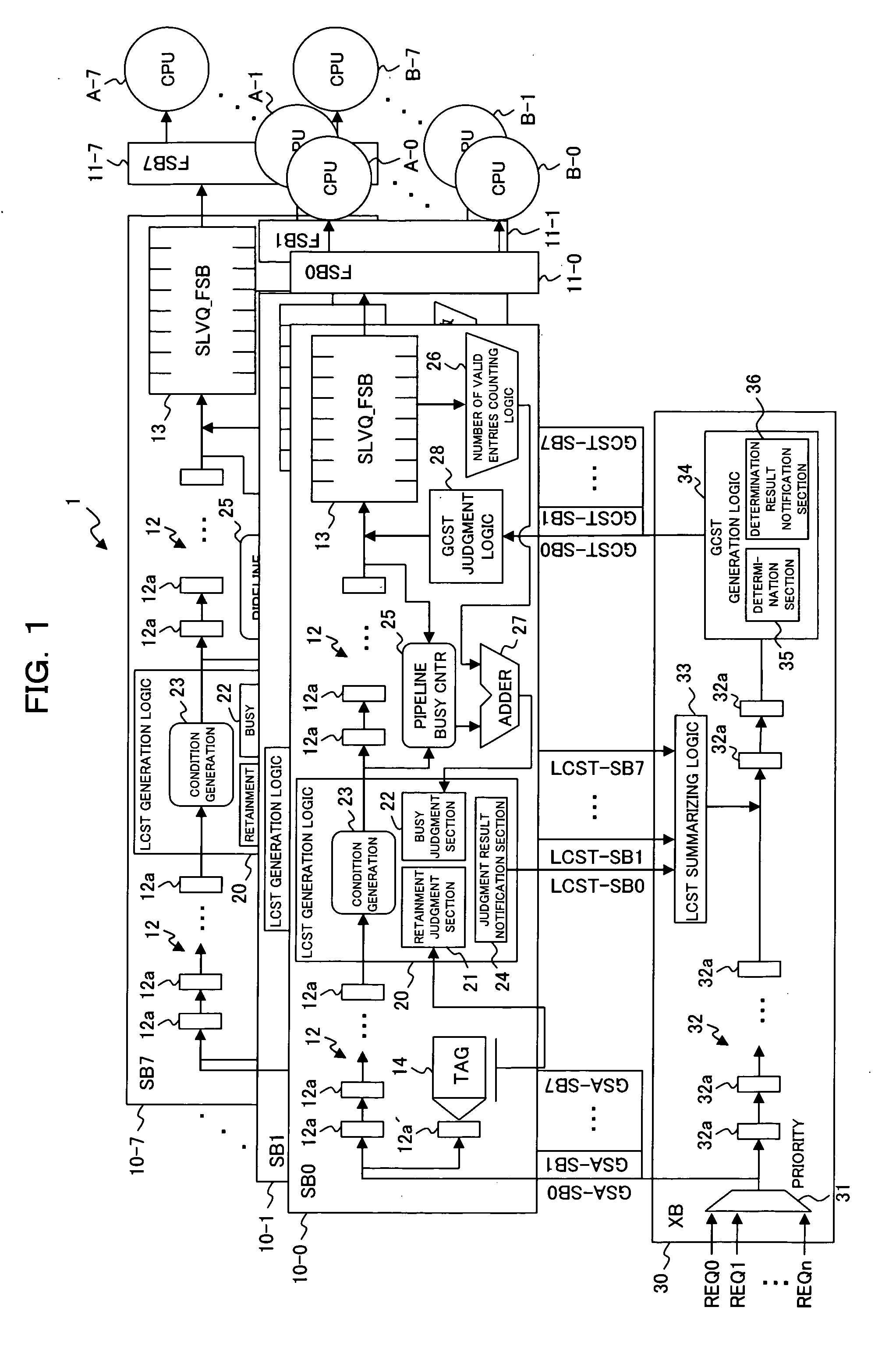
[0064] First, by referring to a block diagram shown in FIG. 1, the configuration of an information processing system 1 in an embodiment of the present invention is explained below.

[0065] As shown in FIG. 1, the information processing system 1 comprises a plurality (eight, here) of pipeline processors (denoted by SB (System Board) in the figure) 10-0 to 10-7, data buses (FSB: Front Side Bus) 11-0 to 11-7, operation sections (denoted by CPU (Central Processing Unit) in the figure) A-0 to A-7 and B-0 to B-7, and a controller (denoted by XB (Crossbar Board) in the figure) 30.

[0066] Each of the plurality of pipeline processors 10-0 to 10-7 (hereinafter, denoted simply by a symbol “10” for description when it is not necessary to distinguish the plurality of pipeline processors 10-0 to 10-7 from each other) is connected to the two operation sections ...


PUM


Abstract

In the present invention, in order that a busy judgment of a register can be made without fail and without increasing the number of hardware resources for storing a request into the register provided at the final stage of a pipeline register in a stage in which the request is retained halfway in the pipeline register in a pipeline processor, a first counter for counting the number of valid requests in the registers between a judgment section interposed in the pipeline register and for judging whether the request is a valid request and a request queue and a busy judgment section for judging whether the request queue is in a busy state based on the number of valid requests counted by the first counter are provided and a judgment is made by the judgment section based on the result of the busy state judgment by the busy judgment section.

Description

BACKGROUND OF INVENTION [0001] 1) Field of the Invention [0002] The present invention relates to a technique for, in a device, for example, provided with a register for retaining a request at the final stage of a pipeline register including a number of multi-stage registers, making a Judgment about the entry (storage) into the register in a stage in which the request is retained halfway in the pipeline register. [0003] 2) Description of the Related Art [0004] Conventionally, there is a pipeline device provided with a queue for retaining a request at the final stage of a pipeline register including a number of multi-stage registers and functioning as a shift register (for example, refer to Patent Document 1 mentioned below). [0005] A conventional information processing system provided with such a pipeline processor is shown in FIG. 9. As shown in FIG. 9, an information processing system 100 comprises a plurality of (eight, here) pipeline processors 110-0 to 110-7 (denoted by SB (Syst...

Claims


Application Information

Patent Timeline
Patent Type & Authority Applications(United States)
IPC IPC(8): G06F15/00
CPCG06F9/3824G06F9/46
Inventor MATSUI, TAKAOHOSOKAWA, YUKAHATAIDA, MAKOTOUEKI, TOSHIKAZUOKADA, SEISHI
Owner FUJITSU LTD
Learn More