A Capacitive Inertial Sensor Digital Servo Circuit

A technology of inertial sensor and digital servo, applied in the direction of instruments, speed/acceleration/shock measurement, measuring devices, etc., can solve problems such as difficult accurate control, poor linearity, and failure to work normally, and achieve the best performance and high flexibility Effect

Active Publication Date: 2018-09-14
INST OF GEOLOGY & GEOPHYSICS CHINESE ACAD OF SCI
View PDF7 Cites 0 Cited by
  • Summary
  • Abstract
  • Description
  • Claims
  • Application Information

AI Technical Summary

Problems solved by technology

However, due to the complexity and particularity of the MEMS manufacturing process, the accuracy of the parameters of the MEMS capacitive inertial sensor itself is poor and the dispersion is large, which often leads to the mismatch of the originally matched loop filter, and the light one leads to digital closed-loop servo The performance of the circuit is degraded, and in serious cases, the digital closed-loop servo circuit is unstable and cannot work normally; the loop filter realized by the analog circuit is due to the error of integrated circuit processing and the existence of parasitic effects, resulting in poor parameter accuracy of the loop filter , it is difficult to accurately control
[0008] Since the single quantizer 1-bit feedback sigma-delta modulator uses a comparator and a 1-bit force feedback control signal generator to generate force feedback control signals, this digital closed-loop servo circuit has relatively large quantization noise, poor linearity, and stability. Poor, the actual maximum detection volume accounts for a small proportion of the entire system design range, etc.

Method used


Image

  • A Capacitive Inertial Sensor Digital Servo Circuit
  • A Capacitive Inertial Sensor Digital Servo Circuit
  • A Capacitive Inertial Sensor Digital Servo Circuit

Examples


Embodiment Construction

[0040] In order to make the object, technical solution and advantages of the present invention clearer, the present invention will be further described in detail below in conjunction with the accompanying drawings and embodiments. It should be understood that the specific embodiments described here are only used to explain the present invention, not to limit the present invention.

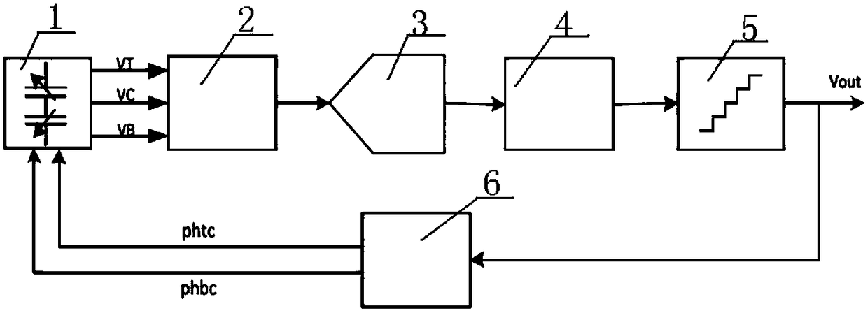
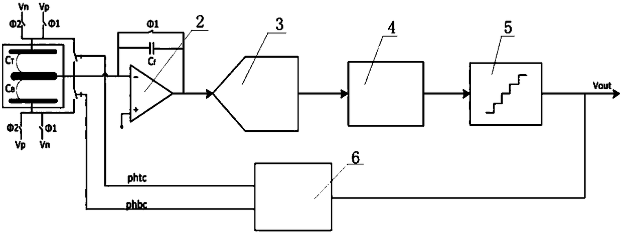
[0041] See attached figure 1 and attached image 3 , is a schematic diagram of a digital servo circuit embodiment of a MEMS sandwich capacitive acceleration sensor provided by the present invention.

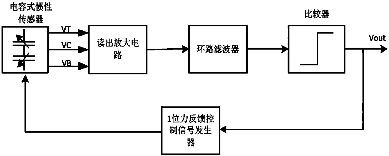
[0042] The digital servo circuit of the MEMS sandwich capacitive acceleration sensor provided by the present embodiment includes: a sandwich capacitive acceleration sensor 1, a readout amplifier circuit 2, an analog-to-digital converter 3 (ADC), a digital loop filter 4, and multi-bit quantization device 5 and pulse width modulation generator 6.

[0043]The capacitive sensor 1 is a MEMS sandwich ca...


PUM


Abstract

The present invention provides a capacitance-type inertial sensor digital servo circuit. The capacitance-type inertial sensor digital servo circuit comprises a capacitance-type sensor, a reading-out amplification circuit, an analog-digital converter (ADC), a digital loop filter, a multi-digit quantizer and a pulse-width modulation generator. The capacitance-type sensor, the reading-out amplification circuit, the analog-digital converter (ADC), the digital loop filter, the multi-digit quantizer and the pulse-width modulation generator are connected in order and form a loop. Through adoption of the digital loop filter, the capacitance-type inertial sensor digital servo circuit is high in flexibility and accuracy; through adoption of the multi-digit quantizer, the capacitance-type inertial sensor digital servo circuit realizes multi-digit quantification and has small quantification noise, high linearity and high duty ratio; and moreover, through adoption of the pulse-width modulation generator, the capacitance-type inertial sensor digital servo circuit generates differential force feedback control signals to realize multi-digit force feedback control so as to greatly reduce the nonlinearity introduced by a common analog-digital converter (DAC) and improve the inhibition capability for common-mode noise.

Description

technical field [0001] The invention belongs to the technical field of sensor control, in particular to a capacitive inertial sensor digital servo circuit. Background technique [0002] Capacitive inertial sensors generally include inertial sensors such as acceleration sensors and gyroscopes. These inertial sensors measure the acceleration of the carrier relative to the ground and other parameters in real time to determine the position of the carrier and the parameters of the earth's gravity field, and the measured changes translates into a change in capacitance. [0003] The following is an example of a MEMS (Micro Electro Mechanical System) capacitive inertial sensor. [0004] With the increasing maturity of MEMS (Micro Electro Mechanical System) technology, MEMS capacitive inertial sensors are widely used due to their small size, high sensitivity, stable DC characteristics, small drift, low power consumption, and small temperature coefficient. However, MEMS The capaciti...

Claims


Application Information

Patent Timeline
Patent Type & Authority Patents(China)
IPC IPC(8): G01P15/125
CPCG01P15/125
Inventor 熊兴崟李宗伟韩可都薛旭杨长春丛宁
Owner INST OF GEOLOGY & GEOPHYSICS CHINESE ACAD OF SCI
Why Eureka
Try Eureka