Synchronization method and program for a parallel computer

a parallel computer and synchronization method technology, applied in the direction of program control, multi-programming arrangements, instruments, etc., can solve the problems complicating the hardware configuration, and pushing up the price of parallel computers. to achieve the effect of lowering the efficiency of parallel processing

Inactive Publication Date: 2006-09-21
HITACHI LTD
View PDF2 Cites 87 Cited by
  • Summary
  • Abstract
  • Description
  • Claims
  • Application Information

AI Technical Summary

Benefits of technology

[0006] In the above example of prior art, a hardware barrier synchronization mechanism provides one signal line to one processor (chip), which allows processors to synchronize on one thread but not on plural threads. This leads to a problem in that, when a multicore microprocessor with plural processor cores mounted to one chip is employed for multithread parallel processing, since, whereas the processors are capable of processing plural threads in parallel, synchronization processing can be performed only on one thread and it lowers the efficiency of parallel processing.

Problems solved by technology

This leads to a problem in that, when a multicore microprocessor with plural processor cores mounted to one chip is employed for multithread parallel processing, since, whereas the processors are capable of processing plural threads in parallel, synchronization processing can be performed only on one thread and it lowers the efficiency of parallel processing.
However, it complicates the hardware configuration and pushes up the price of a parallel computer extremely high.
Furthermore, in the case where one processor core is assigned plural threads (multithread parallel processing), the hardware barrier synchronization mechanism is capable of synchronization only on one of the plural threads, the efficiency of multithread parallel processing is lost.

Method used


Image

  • Synchronization method and program for a parallel computer
  • Synchronization method and program for a parallel computer
  • Synchronization method and program for a parallel computer

Examples


first embodiment

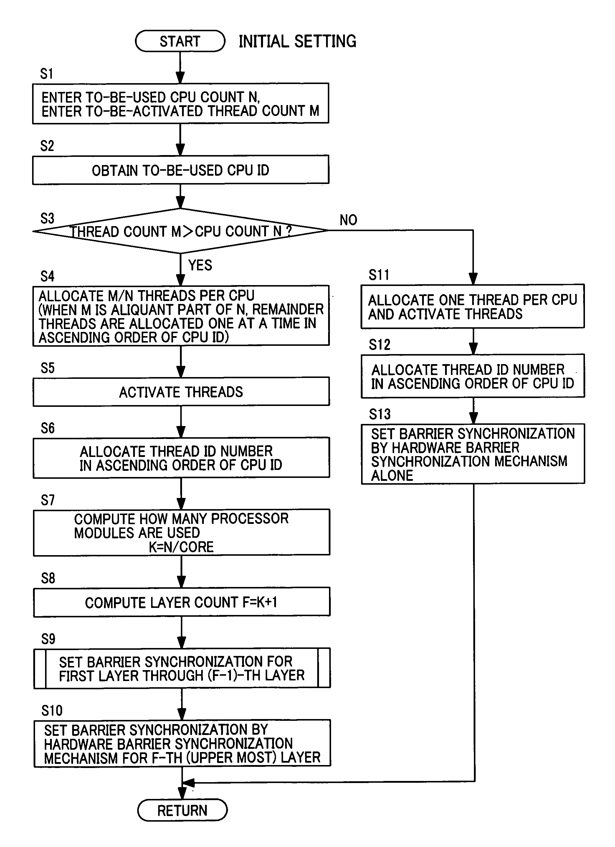
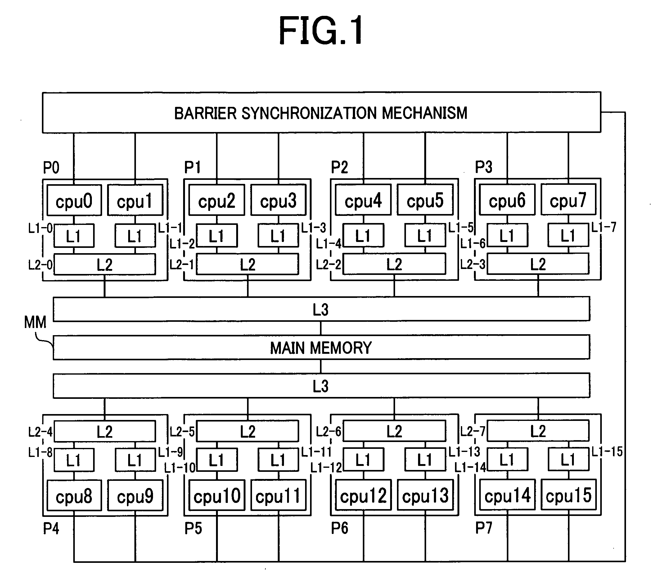
[0039]FIG. 1 shows an example of constructing a parallel computer from a shared memory multiprocessor system with a multicore microprocessor to which a first embodiment of this invention is applied.

[0040]

[0041] A parallel computer of FIG. 1 has a multiprocessor composed of plural processor modules (processors) P0 to P7. Plural processor cores (cpu0 to cpu15 of FIG. 1) are mounted to each of the processor modules P0 to P7. Two processor cores are mounted to the processor module P0. The processor module P0 has, for example, the processor cores cpu0 and cpu1, and is capable of running two CPUs in parallel.

[0042] The processor cores cpu0 and cpu1 have primary cache memories (hereinafter referred to as primary caches) L1-0 and L1-1, respectively, which are independent of each other. The primary caches L1-0 and L1-1 of the two processor cores cpu0 and cpu1 are connected to one secondary cache memory (hereinafter referred to as secondary cache) L2-0 provided in the processor module P0. T...

second embodiment

[0161] FIGS. 15 to 20 illustrate a second embodiment of this invention in which software alone is used in barrier synchronization without the help of the hardware barrier synchronization mechanism 100 shown in the first embodiment.

[0162]FIG. 15 shows the hardware configuration of a parallel computer according to the second embodiment. The parallel computer of this embodiment is obtained by removing the hardware barrier synchronization mechanism 100 from the parallel computer of the first embodiment shown in FIG. 1, and the rest of the configuration is the same as in the first embodiment.

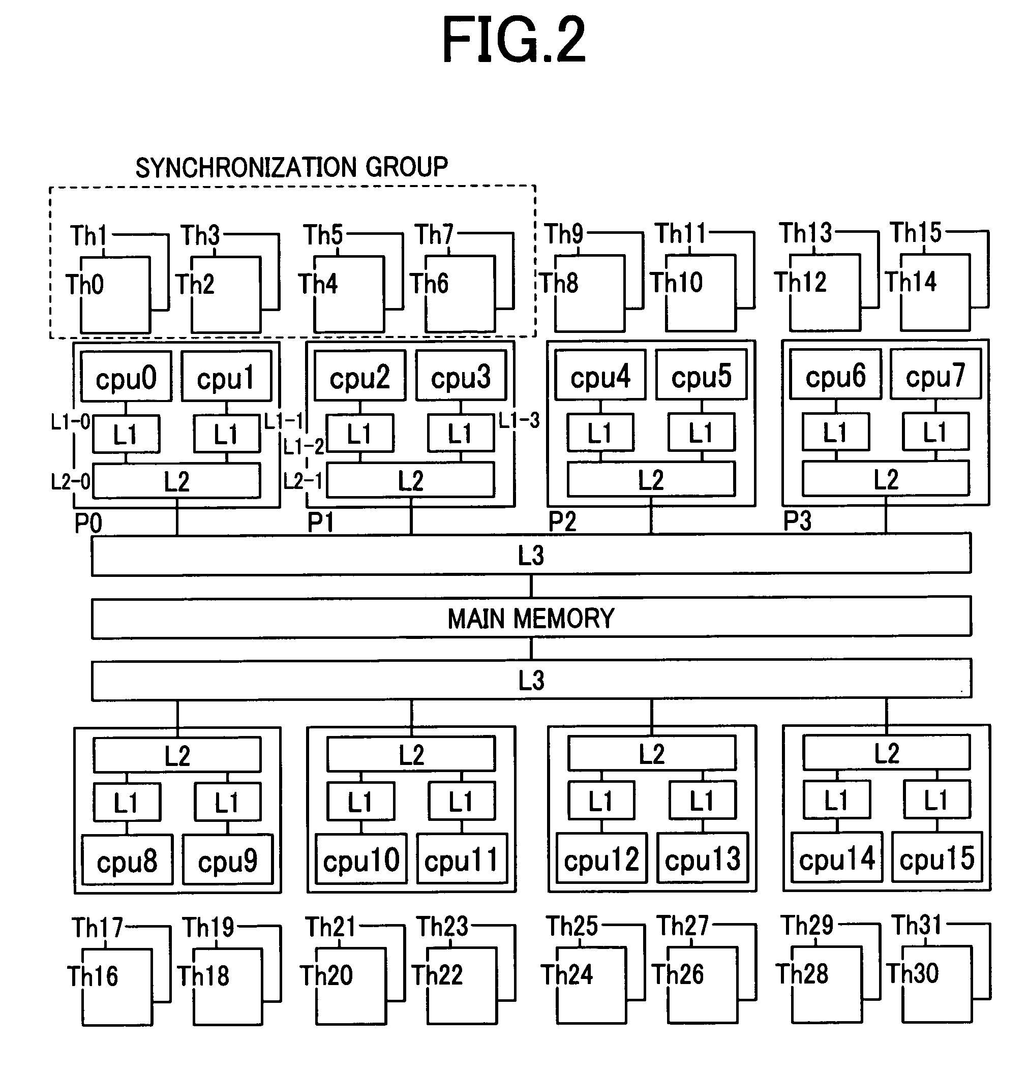
[0163]FIG. 16 shows an example of the synchronization group Gr. FIG. 16 is similar to FIG. 4 referred to in the first embodiment in that the drawing shows details of the synchronization group Gr for when four processor cores cpu0 to cpu3 are assigned eight threads Th0 to Th7 to receive barrier synchronization.

[0164] The first layer, which is the lowermost layer of the synchronization group Gr, mak...

third embodiment

[0212]FIGS. 22 and 23 show a third embodiment in which the barrier synchronization processing described in the first embodiment is carried out by dedicated threads while other threads are dedicated to parallel computation processing. The rest of the configuration of the third embodiment is the same as the first embodiment.

[0213] The processor cores cpu0 to cpu3 are assigned and execute threads Th0 to Th7, which perform computation processing alone and function as child threads, and synchronization threads Sth0 to Sth3, which function as parent threads in each layer and perform barrier synchronization processing alone. The synchronization threads Sth0 to Sth3 execute only the barrier synchronization processing in the computation processing PG2 of the program PG shown in FIG. 6. The computation threads Th0 to Th7 execute computation processing (parallel computation processing) of the program PG and only a part of barrier synchronization processing.

[0214] The computation threads Th0 ...


PUM


Abstract

Barrier synchronization between multiprocessors is performed at high speed while reducing overhead of parallel processing without adding any special hardware mechanism. A parallel computer synchronization method is provided to synchronize threads through barrier synchronization for parallel execution of plural threads on plural processor modules. The parallel computer has plural processor modules (P0 and P1) equipped with plural processor cores (cpu0 to cpu3). The processor cores are each assigned plural threads (Th0 to Th7) to execute multithread processing. The plural threads (Th0 to Th7) are set in hierarchical groups (Gr), and barrier synchronization is performed on each group separately.

Description

CLAIM OF PRIORITY [0001] The present application claims priority from Japanese application P2005-72633 filed on Mar. 15, 2005, the content of which is hereby incorporated by reference into this application. BACKGROUND OF THE INVENTION [0002] This invention relates to barrier synchronization processing in a parallel computer and, more specifically, a computer capable of multiple barrier synchronization operations. [0003] Barrier synchronization is common in parallel computers in which plural processors are each assigned a thread (or process) to compute separately. Through barrier synchronization processing, the processors are synchronized with one another at a barrier synchronization point set to each thread in advance. [0004] For example, in a Symmetric Multiprocessing (SMP) parallel computer, plural symmetric multiple processors share a memory, which enables a thread on each processor to access data stored in the shared memory by other threads and to exchange computation results wi...

Claims


Application Information

Patent Timeline
Patent Type & Authority Applications(United States)
IPC IPC(8): G06F9/46
CPCG06F9/52G06F9/522
Inventor TAKAYAMA, KOICHIAOKI, HIDETAKA
Owner HITACHI LTD
Why Eureka
Try Eureka