

Stent crimping mechanisms
a crimping mechanism and stent technology, applied in the direction of prosthesis, forging/pressing/hammering apparatus, shape tools, etc., can solve the problems of reducing the life of fingers, stent and/or iris fingers may be damaged, and so as to reduce the number of blade “gaps” and the effect of reducing the possibility of pinching or damaging the sten
- Summary
- Abstract
- Description
- Claims
- Application Information
AI Technical Summary
Benefits of technology
Problems solved by technology
Method used
Image

Examples
Embodiment Construction
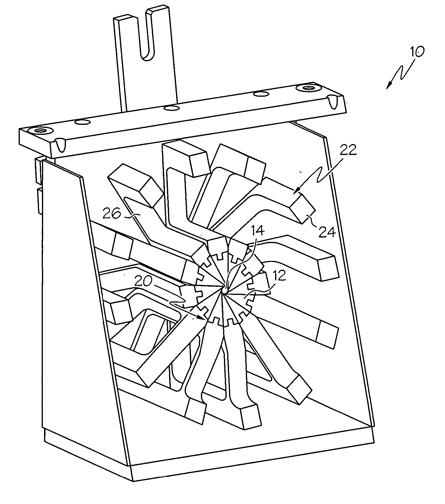
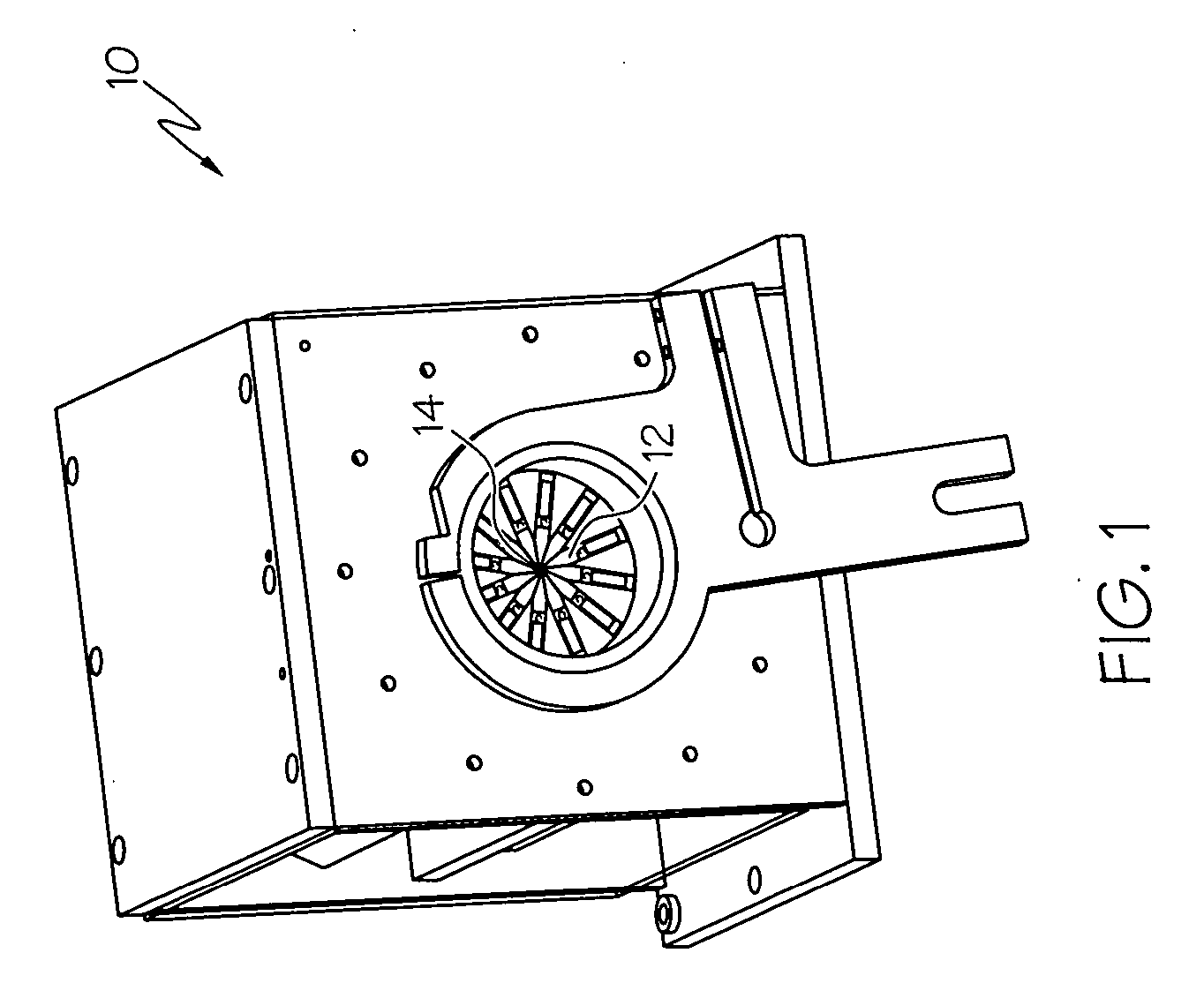
[0039] As indicated above, the present invention is embodied in a variety of forms. In at least one embodiment, such as for example in the embodiment depicted in FIG. 1, the invention is directed to a radial stent reducing assembly or crimper 10.
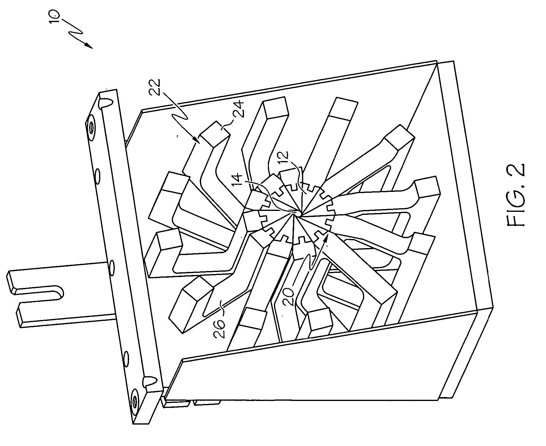
[0040] In the embodiment shown, crimper 10 is provided with a plurality of stent reducing members or blades 12 which define a stent reduction chamber or iris opening 14 into which a stent or other medical device (not shown) may be positioned in order to reduce the stent from an unreduced diameter state. Unlike many prior stent crimping devices, the crimper 10 in the embodiment shown in FIGS. 1-7 is constructed and arranged to provide minimal to no spacing between the adjacent blades 12, or at least between portions of the blade that are in close proximity to the stent during the crimping process, such as is sown in FIGS. 4-6.
[0041] As is shown in FIG. 2, the components of the crimper 10, include actuation elements or fingers 20 which may b...
PUM
| Property | Measurement | Unit |
|---|---|---|
| Diameter | aaaaa | aaaaa |
Abstract
Description
Claims
Application Information