Method for making a heat pipe

a heat pipe and heat pipe technology, applied in semiconductor devices, lighting and heating apparatus, semiconductor devices, etc., can solve the problems of reducing the speed of condensed working fluid, limiting the heat transfer performance of the heat pipe, and not always the best way to choose a screen mesh with small pores, etc., to achieve a large capillary pressure and reduce flow resistance

Inactive Publication Date: 2006-09-28
HON HAI PRECISION IND CO LTD
View PDF11 Cites 31 Cited by
  • Summary
  • Abstract
  • Description
  • Claims
  • Application Information

AI Technical Summary

Benefits of technology

[0008] According to a preferred embodiment of the present invention, a method for making a heat pipe includes the following steps: a) providing a screen mesh in the form of a multi-portion structure with at least one portion thereof having an average pore size different from that of the other portions; b) rolling the screen mesh into column form; c) positioning the screen mesh into a pipe body of the heat pipe; d) sintering the screen mesh received in the pipe body at a predete

Problems solved by technology

However, it is not always the best way to choose a screen mesh having small-sized pores, because the flow resistance to the condensed working fluid also increases due to the decrease in pore size of the screen mesh.
The increased flow resistance reduces the speed of the condensed working fluid in returning back to the evapora

Method used


Image

  • Method for making a heat pipe
  • Method for making a heat pipe
  • Method for making a heat pipe

Examples


Embodiment Construction

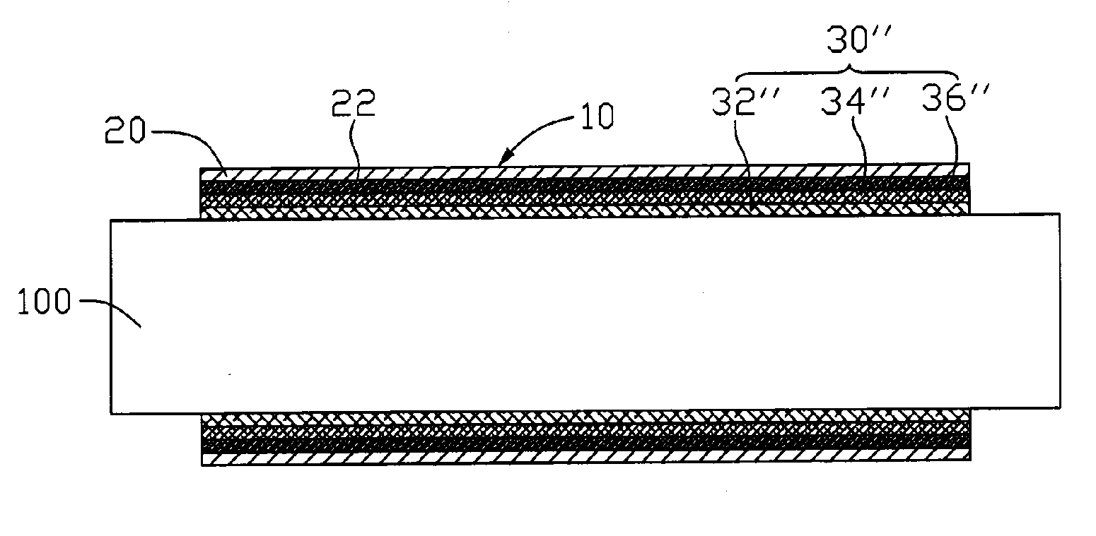
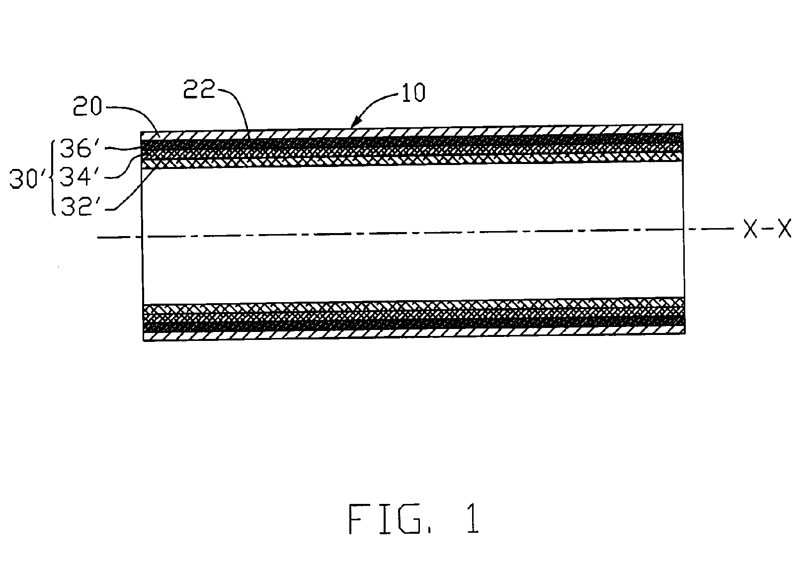
[0020]FIG. 1 illustrate a heat pipe 10 formed in accordance with a method of the present invention. The heat pipe 10 is vacuumed and includes a pipe body 20 and a wick structure 30′ of a screen mesh arranged against an inner wall 22 of the pipe body 20. The heat pipe 10 is divided into an evaporating section, an adiabatic section and a condensing section along an axial direction of the heat pipe 10. The adiabatic section is located between the evaporating and condensing sections.

[0021] The pipe body 20 is made of high thermally conductive material such as copper or aluminum. Although the pipe body 20 illustrated is in a round shape, it should be recognized that other shapes, such as polygon, rectangle, or triangle, may also be suitable. Although it is not shown in the drawings, it is well known by those skilled in the art that two ends of the pipe body 20 are sealed.

[0022] The wick structure 30′ is saturated with a working fluid (not shown), which acts as a heat carrier when under...


PUM

PropertyMeasurementUnit
Pore sizeaaaaaaaaaa
Lengthaaaaaaaaaa
Electrical resistanceaaaaaaaaaa

Abstract

A method (50) for making a heat pipe (10) includes the following steps: a) providing a screen mesh (30) in the form of a multi-portion structure with at least one portion having an average pore size different from that of the other portions; b) rolling the screen mesh into a hollow column form; c) inserting the screen mesh into a hollow pipe body (22) of the heat pipe; d) sintering the screen mesh received therein at a predetermined temperature; and e) filling a working fluid into the pipe body and sealing the pipe body. The portion with large-sized pores is capable of reducing the flow resistance to a condensed fluid to flow back, whereas the portion with small-size pores is capable of providing a relatively large capillary pressure for drawing the condensed fluid from the condensing section to the evaporating section of the heat pipe.

Description

FIELD OF THE INVENTION [0001] The present invention relates generally to a heat pipe as a heat transfer device, and more particularly to a method for making a heat pipe with a wick structure of screen mesh. DESCRIPTION OF RELATED ART [0002] As electronic industry continues to advance, electronic components such as central processing units (CPUs), are made to provide faster operation speeds and greater functional capabilities. When a CPU operates at a high speed, its temperature frequently increases greatly. It is desirable to dissipate the heat generated by the CPU quickly. [0003] To solve this problem of heat generated by the CPU, a cooling device is often used to be mounted on top of the CPU to dissipate heat generated thereby. It is well known that heat absorbed by fluid having a phase change is ten times more than that the fluid does not have a phase change; thus, the heat transfer efficiency by phase change of fluid is better than other mechanisms, such as heat conduction or he...

Claims


Application Information

Patent Timeline
IPC IPC(8): B23P6/00
CPCB23P15/26B23P2700/10F28D15/046H01L21/4882Y10T29/49353H01L2924/0002H01L23/427H01L2924/00
Inventor WU, JUNG-YUANHONG, CHU-WANCHENG, CHING-TAILO, CHANG-TING
Owner HON HAI PRECISION IND CO LTD
Why Eureka
Try Eureka