Pile driver

a technology of driver and ram, which is applied in the field of ram drivers, can solve the problems of reducing the possibility of operator error, reducing the possibility of ram striking the frame, and reducing the overhead spa

Inactive Publication Date: 2006-09-28
HERCULES MACHINERY
View PDF26 Cites 25 Cited by
  • Summary
  • Abstract
  • Description
  • Claims
  • Application Information

AI Technical Summary

Benefits of technology

[0009] Another form of the invention includes an apparatus for allowing relative movement between the hammer and, e.g., the boom of an excavator. In one embodiment, the apparatus includes at least one frame rail mounted to the hammer frame and a mounting plate assembly that interfits with and is slidable with respect to the frame rail mounted to the boom of an excavator. In one embodiment, the mounting plate assembly includes a recess that envelops the frame rail. In an alternative embodiment, the mounting plate assembly is enveloped by the frame rail. In the present embodiment, the mounting plate assembly interfits with the frame rail in such a way that the mounting plate assembly can slide along an axis defined by the rail. The mounting plate assembly can be further constructed to prevent substantial relative movement between the hammer and the mounting plate assembly transverse to the rail axis. In a further embodiment, the apparatus can permit relative rotational movement between the hammer and the boom of an excavator. This embodiment may be helpful when the excavator is sitting on an inclined surface.
[0010] In operation, in one form of the invention, the hammer is placed on top of the pile and, as the pile is driven downwardly, the hammer follows the pile owing to the relative movement between the excavator boom and the hammer. Advantageously, the hammer can follow the pile without requiring continuous downward readjustment of the boom. However, the boom is adjusted periodically when the mounting plate reaches an end of the hammer frame rail. As a result, the possibility of operator error is reduced as fewer adjustments of the boom are required. Further, pile drivers incorporating this apparatus are an improvement over existing pile drivers as the possibility of the ram striking the frame is also reduced. In one embodiment, the mounting plate assembly does not extend substantially above the hammer frame. This embodiment provides an added advantage of allowing the hammer to be used inside buildings, etc, having very little overhead room.

Problems solved by technology

However, in existing hammers, as the ram strikes the pile, significant forces are transmitted into the cylinder through a cylinder rod attached to the ram.
As a result, these cylinders frequently break resulting in significant downtime and cost to replace the cylinder.
Some existing hammers include a nylon or rubber mount at the connection between the ram and cylinder rod to dampen these forces, however, these mounts can deteriorate quickly.
This force may be transferred from the frame into the boom of an excavator, e.g., causing damage to the excavator and possibly causing the excavator to tip over.
However, these outer frames required significant overhead room to position the hammer, thus, pile drivers utilizing these outer frames were mostly limited to outdoor applications.

Method used


Image

  • Pile driver
  • Pile driver
  • Pile driver

Examples


Embodiment Construction

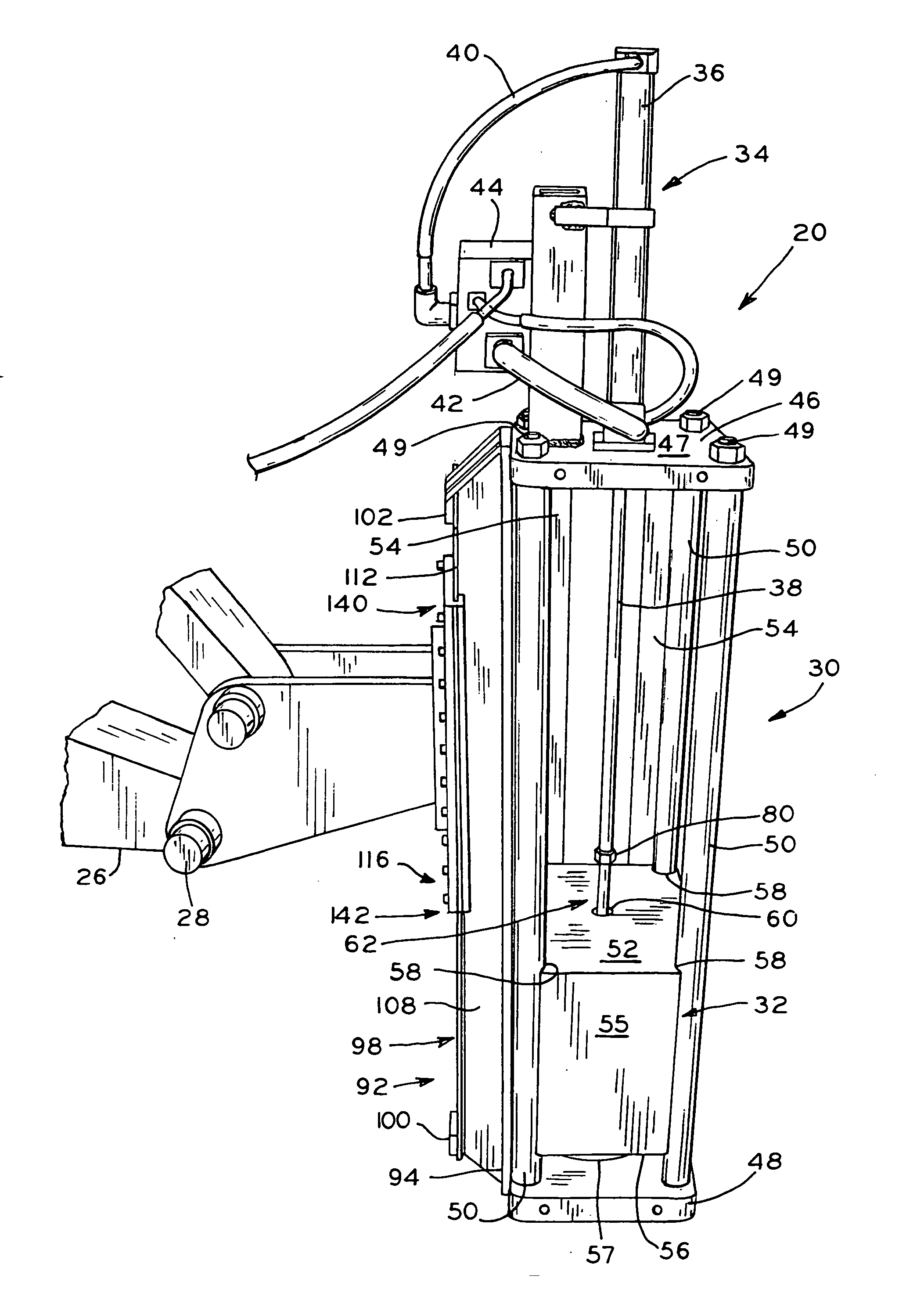
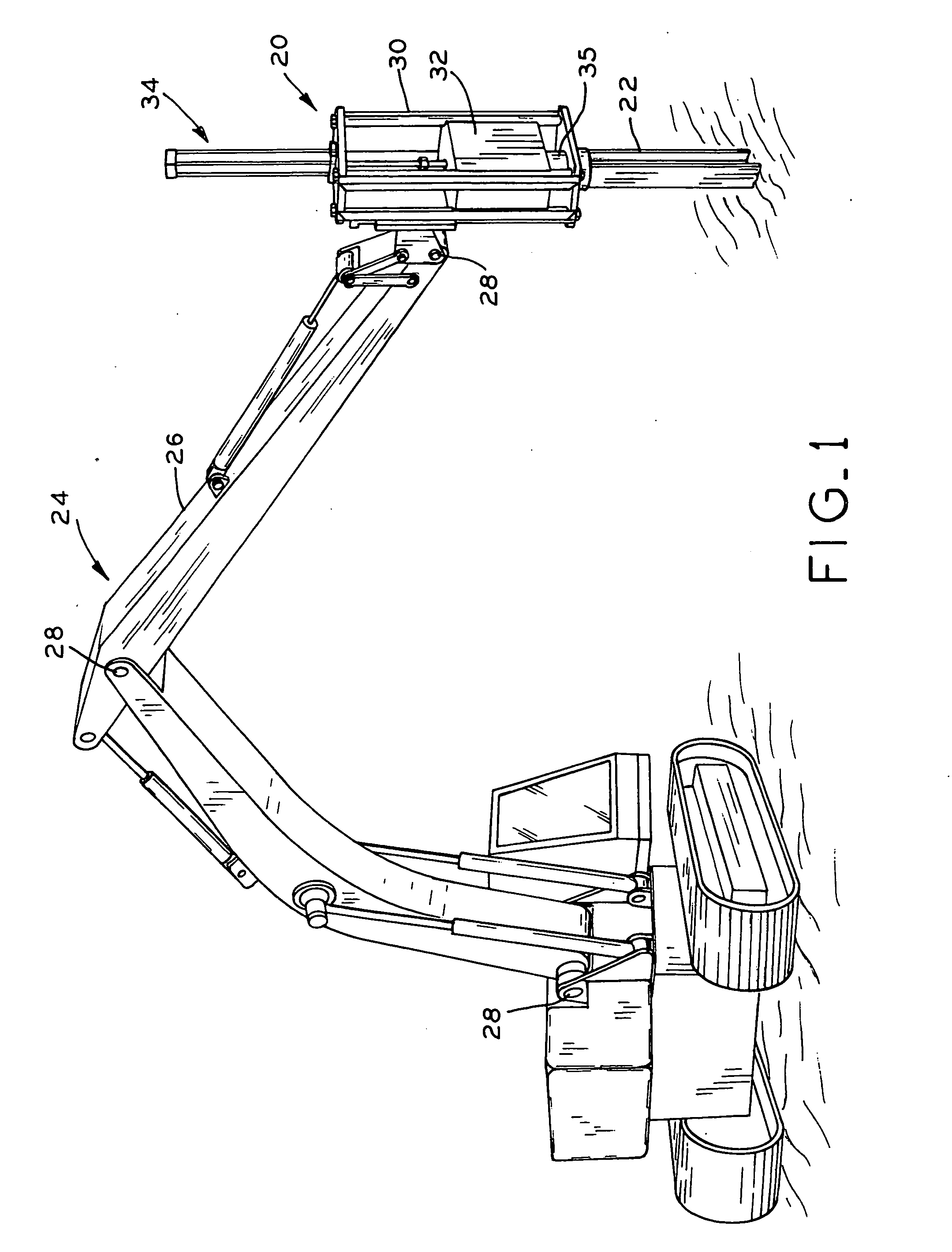
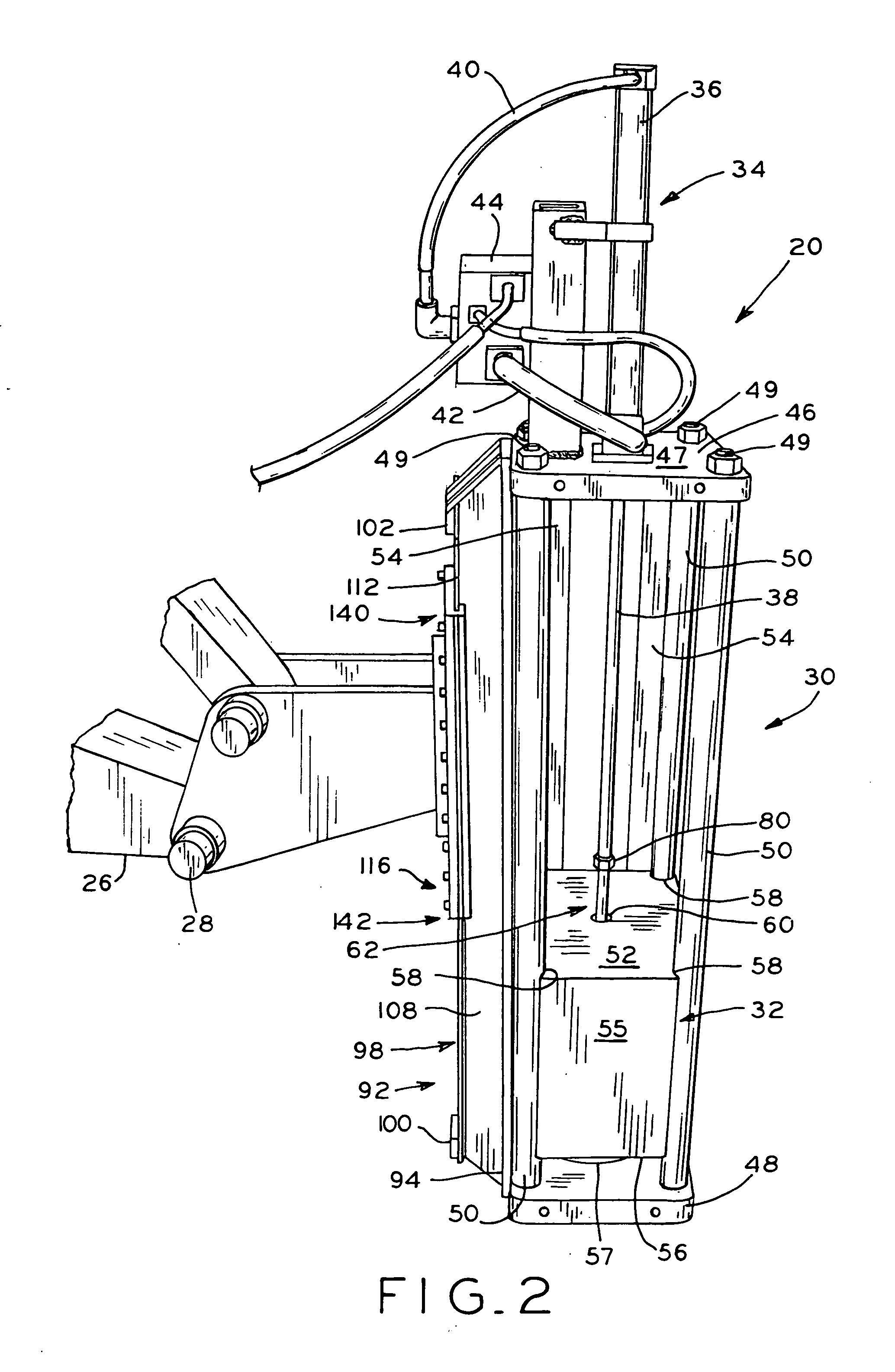
[0029] As illustrated in FIG. 1, hammer 20, in operation, is placed on top of pile 22 by excavator 24. Excavator 24 includes boom 26 that articulates at several joints 28, as is well known in the art, to position hammer 20. In the present embodiment, hammer 20 includes frame 30, ram 32 positioned within frame 30, and a ram lifting mechanism in the form of cylinder assembly 34 mounted to the top of frame 30. In operation, ram 32 is raised by hydraulic or pneumatic cylinder assembly 34 and then dropped onto pile 22. Commonly, a drive cap (not illustrated) is placed over the end of the pile to reduce deformation, or mushrooming, of the top of the pile. The drive cap includes a substantially flat upper surface and a recess in a bottom surface that mates with the top of the pile. When a drive cap is used, hammer frame 30 rests on top of the upper surface of the drive cap. Piles typically include a consistent H-shaped or I-shaped cross-section, e.g., that extend along the length of the pi...


PUM


Abstract

A pile driver including an apparatus for allowing relative movement between a hammer and a boom of an excavator. The apparatus includes a mounting plate mounted to the boom that interfits with and is slidable with respect to a frame rail mounted to the hammer. In operation, the hammer is placed on top of a pile and, as the pile is driven downwardly, the hammer follows the pile. Owing to the relative movement between the boom of the excavator and the hammer, the hammer follows the pile without requiring continuous downward readjustment of the boom. In one embodiment, the mounting plate assembly does not extend substantially above the hammer frame. In another embodiment, the hammer can rotate with respect to the boom. In one embodiment, the hammer includes a ram, a cylinder for lifting the ram, and rotation-resistant cable connecting the ram and the cylinder.

Description

CROSS REFERENCE TO RELATED APPLICATIONS [0001] This application claims the benefit under 35 U.S.C. §119(e) of U.S. Provisional Patent Application Ser. No. 60 / 659,711, entitled PILE DRIVER, filed on Mar. 8, 2005 and U.S. Provisional Patent Application Ser. No. 60 / 661,104, entitled PILE DRIVER, filed on Mar. 11, 2005, the entire disclosures of which are hereby expressly incorporated by reference herein.BACKGROUND OF THE INVENTION [0002] 1. Field of the Invention [0003] The present invention relates to pile drivers, particularly with regard to reciprocating pile drivers. [0004] 2. Description of the Related Art [0005] Pile drivers are used to drive piles, such as beams, columns or supports, e.g., into the ground. Reciprocating pile drivers include a hammer that is placed onto the head, or top, of the pile by a hoist or a boom of, e.g., an excavator. The hammer typically includes a frame and a large ram, or weight, that is raised within the frame and then dropped onto the pile head. Thi...

Claims


Application Information

Patent Timeline
Patent Type & Authority Applications(United States)
IPC IPC(8): B23Q5/00
CPCE02D7/10
Inventor JINNINGS, JOHNGUSTIN, MARK
Owner HERCULES MACHINERY
Why Eureka
Try Eureka