Liquid crystal device and electronic apparatus

a liquid crystal device and electronic equipment technology, applied in non-linear optics, instruments, optics, etc., can solve the problems of distortion in the electric field generated between the first electrode and the second electrode, poor design freedom of the structure, etc., and achieve the effect of high contras

Inactive Publication Date: 2006-09-28
JAPAN DISPLAY WEST
View PDF7 Cites 94 Cited by
  • Summary
  • Abstract
  • Description
  • Claims
  • Application Information

AI Technical Summary

Benefits of technology

[0023] According to a further aspect of the invention, there is provided an electronic apparatus including the liquid crystal de...

Problems solved by technology

As such, the structure has poor freedom in design, such as when attempts are made to differ the area ratio between the reflective display region and the transmissive display region within a single dot region.
Therefore, in the liquid crystal device whi...

Method used


Image

  • Liquid crystal device and electronic apparatus
  • Liquid crystal device and electronic apparatus
  • Liquid crystal device and electronic apparatus

Examples


first embodiment

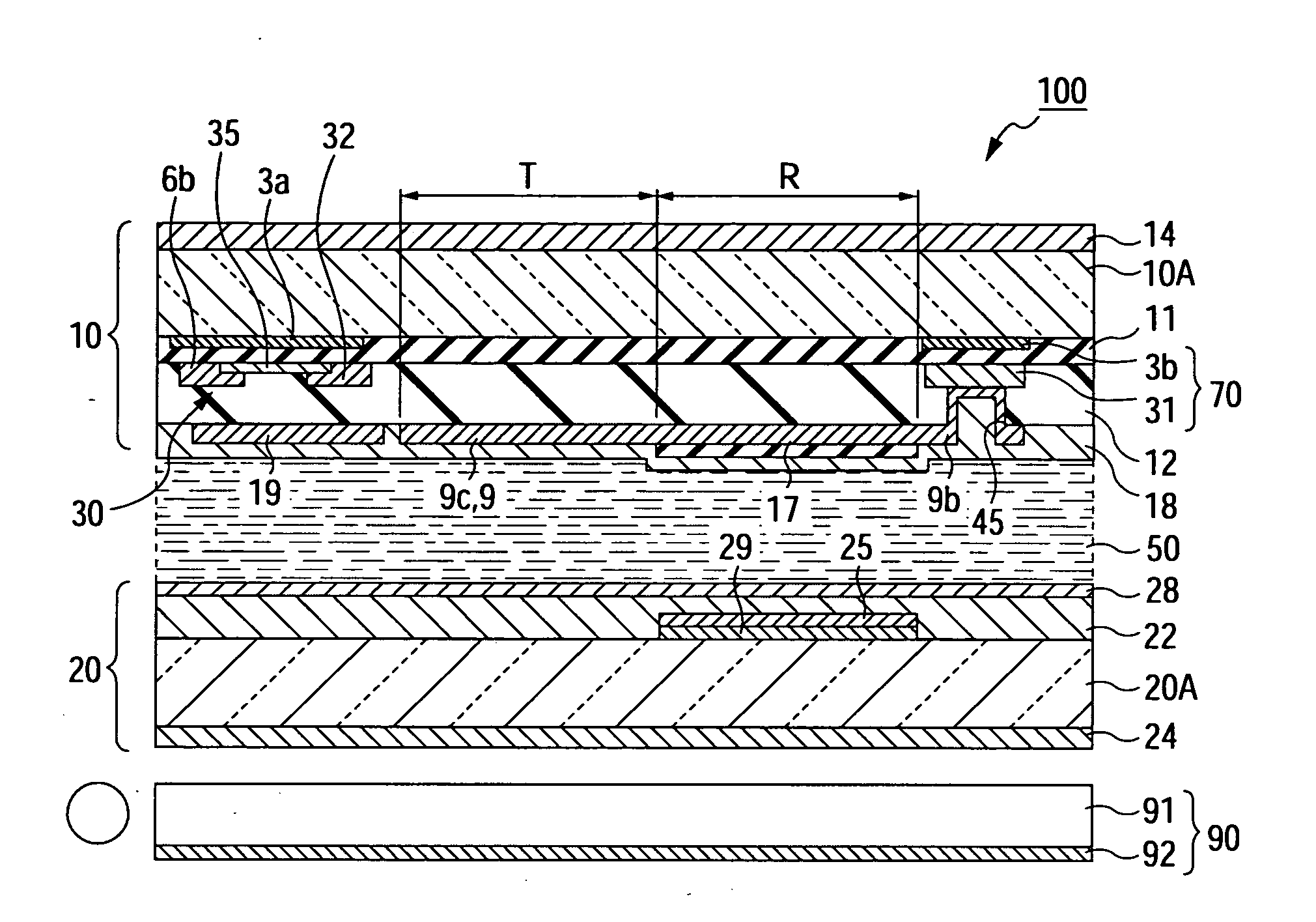
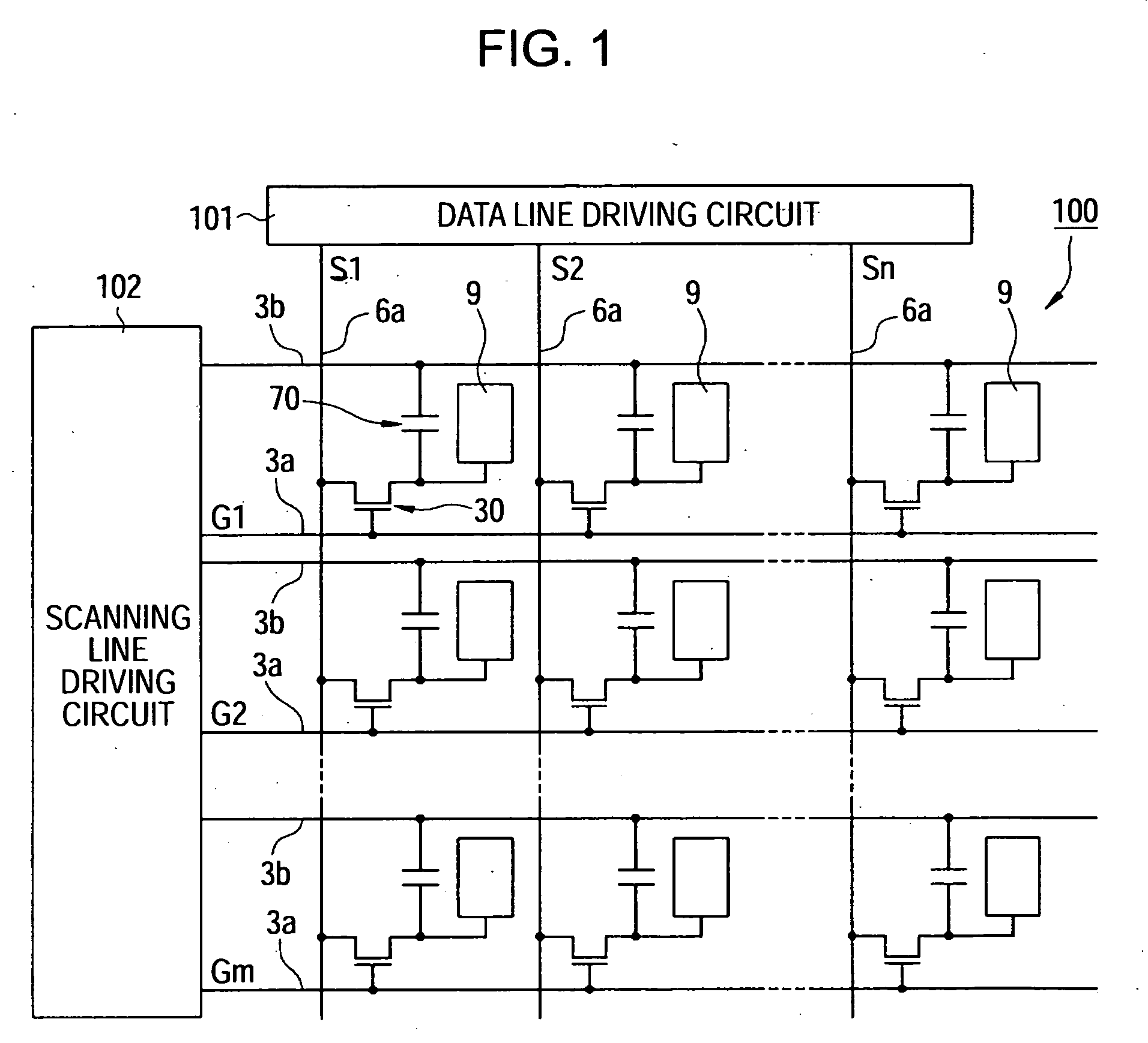
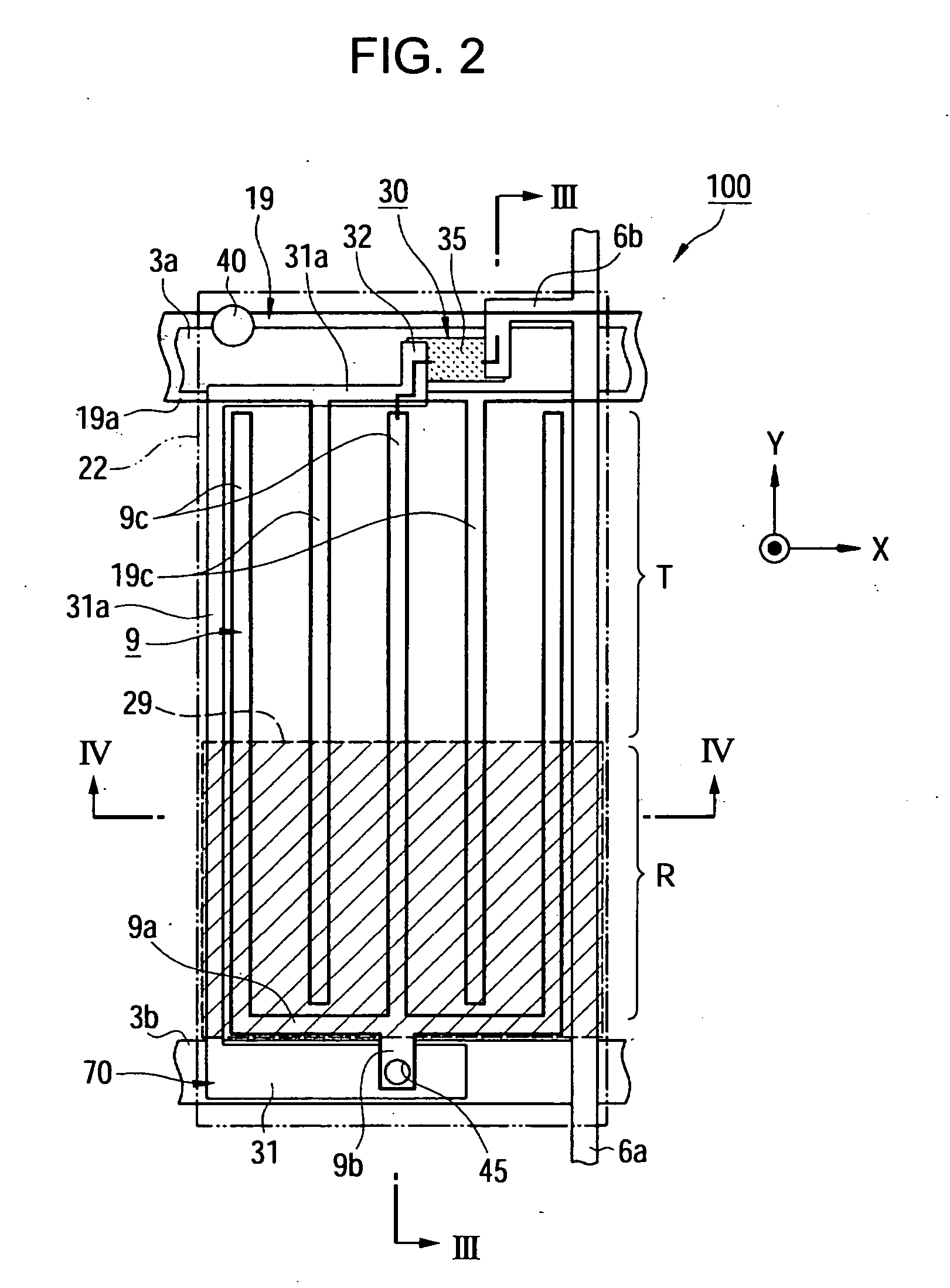
[0039] Hereinafter, a liquid crystal device according to a first embodiment of the invention will be described with reference to the accompanying drawings. The liquid crystal device according to the present embodiment is a liquid crystal device that uses an in-plane switching (IPS) mode among transverse electric field modes in which image display is performed by applying an in-plane electric field (transverse electric field) to liquid crystal to control alignment of liquid crystal molecules.

[0040] In addition, the liquid crystal device according to the present embodiment is a color liquid crystal device that has color filters provided on a substrate. The liquid crystal device has a structure in which one pixel is composed of three dots that output light of three primary colors including R (red), G (green), and B (blue), respectively. Accordingly, in the following description, a display region serving as a minimum unit constituting display is called ‘a dot region’, and a display reg...

second embodiment

[0067] Next, a second embodiment of the invention will be described with reference to FIGS. 6 and 7. The liquid crystal device according to the second embodiment has the same base structure as the liquid crystal device 100 according to the first embodiment. The liquid crystal device according to the second embodiment has a structure in which the step of the surface of the TFT array substrate 10 caused by the reflective portion dielectric film 17 selectively formed in the reflective display region R can be removed.

[0068]FIGS. 6A to 6D are diagrams illustrating a plurality of types in the sectional structure of the TFT array substrate 10 according to the second embodiment of the invention. FIGS. 6A to 6D illustrate only a portion corresponding to the region where the pixel electrode 9 is formed, in the sectional structure of the liquid crystal device taken along the line III-III of FIG. 3. In FIGS. 6A to 6D, the alignment film 18, which is formed so as to cover the pixel electrode 9,...

third embodiment

[0083] Next, a third embodiment of the invention will be described with reference to FIGS. 8 to 10.

[0084]FIG. 8 is a diagram illustrating a planar structure of one dot region of the liquid crystal device 300 according to the third embodiment of the invention. FIG. 9 is a diagram illustrating a sectional structure of the liquid crystal device taken along the line IX-IX of FIG. 8. FIG. 10 is a diagram schematically illustrating a sectional structure of the TFT array substrate 10 in order to explain the effect in the liquid crystal device 300 according to the third embodiment of the invention.

[0085] The liquid crystal device according to the present embodiment is a liquid crystal device that uses a mode called a fringe field switching (FFS) mode among transverse electric field modes in which image display is performed by applying an electric field (transverse electric field) to liquid crystal in a substantially horizontal direction to a surface of a substrate and controlling alignmen...


PUM


Abstract

A liquid crystal device in which a reflective display region for performing reflective display and a transmissive display region for performing transmissive display are provided in one dot region, includes a first substrate and a second substrate disposed so as to be opposite to each other with a liquid crystal layer interposed therebetween; a first electrode and a second electrode provided on a surface of the first substrate which faces the liquid crystal layer, each of the first and second electrodes applying an in-plane electric field to the liquid crystal layer in the one dot region, and a reflective portion dielectric film provided on the first electrode and/or the second electrode in the reflective display region, the reflective portion dielectric film making a capacitance between the first and second electrodes in the reflective display region smaller than a capacitance between the first and second electrodes in the transmissive display region.

Description

BACKGROUND [0001] 1. Technical Field [0002] The present invention relates to a liquid crystal device and to an electronic apparatus. [0003] 2. Related Art [0004] As an example of a liquid crystal device, a liquid crystal device using a transverse electric field mode has been known. In the transverse electric field mode, alignment of liquid crystal molecules is controlled by applying an in-plane electric field to a liquid crystal layer. Specifically, liquid crystal devices using modes, which are called an in-plane switching (IPS) mode and a fringe-field switching (FFS) mode in accordance with a type of an electrode for applying an electric field to liquid crystal, have been known. Recently, a transflective liquid crystal device using a transverse electric field mode has been presented (for example, see ‘Electro-optic Characteristics of In-Plane Driven Transflective LCD’, I. H. Yu et. al., IDW'04, LCT p 2-5) (hereinafter, referred to as I. H. Yu et. al). [0005] However, in the transfl...

Claims


Application Information

Patent Timeline
IPC IPC(8): G02F1/1335
CPCG02F1/133555G02F1/13439G02F2202/42G02F1/1335
Inventor MATSUSHIMA, TOSHIHARUKANEKO, HIDEKI
Owner JAPAN DISPLAY WEST
Why Eureka
Try Eureka