High sensitivity optical detection by temperature independent differential polarization surface plasmon resonance

Inactive Publication Date: 2006-09-28
BIO TELL
View PDF9 Cites 17 Cited by
  • Summary
  • Abstract
  • Description
  • Claims
  • Application Information

AI Technical Summary

Problems solved by technology

Thus, any spurious change in transmitted light cannot be distinguished from a real signal.
Current SPR sensors are sometimes disadvantageous because of their sensitivity to ambient tem

Method used


Image

  • High sensitivity optical detection by temperature independent differential polarization surface plasmon resonance
  • High sensitivity optical detection by temperature independent differential polarization surface plasmon resonance
  • High sensitivity optical detection by temperature independent differential polarization surface plasmon resonance

Examples


Embodiment Construction

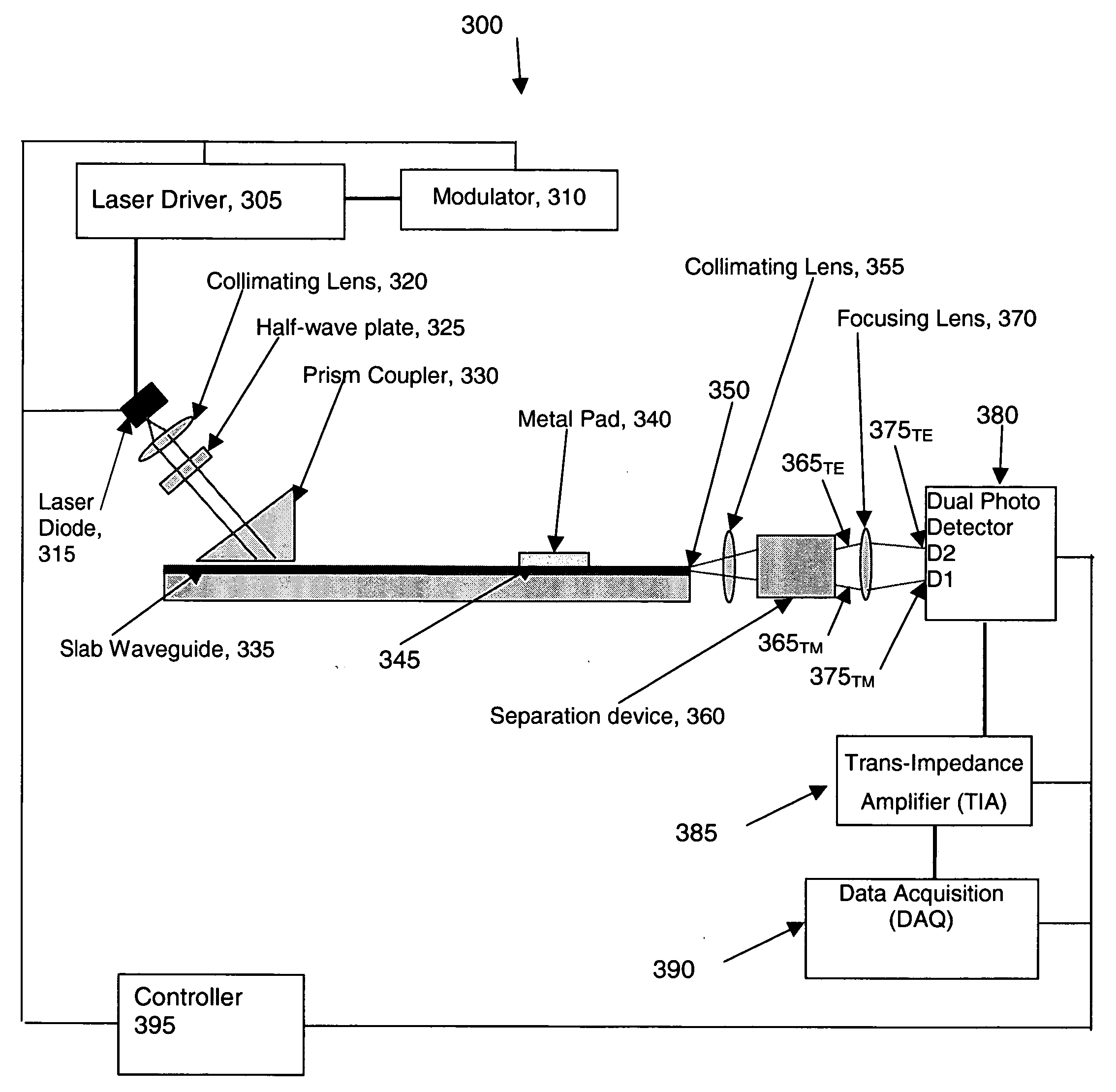
[0020]FIG. 3 shows a block diagram of a system 200 suitable for practicing the embodiments disclosed herein. Although the presently disclosed embodiments will be described with reference to the drawings, it should be understood that the embodiments may be realized in many alternate forms, utilizing any suitable size, shape or type of elements or materials.

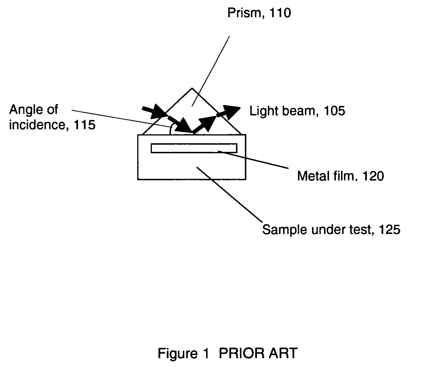
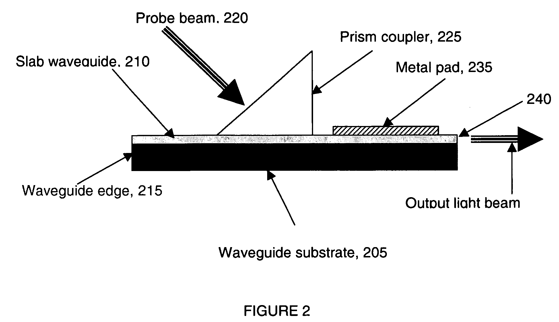
[0021] The disclosed embodiments include an SPR detector based on a slab waveguide design, rather than a set of channel waveguides. The slab waveguide SPR detector design at the very least eliminates the highly precise angle measurement and stabilization required by Kretschmann configurations.

[0022] The disclosed embodiments also include a differential detection scheme based on measuring the instantaneous difference in intensities of transverse magnetic (TM) and transverse electric (TE) polarization modes of a probing light beam. The TM polarized light excites the SPW in the metal film and its transmitted intensity strongly depen...


PUM


Abstract

Detecting an amount of change in light intensity caused by surface plasmon resonance includes coupling light having transverse magnetic and transverse electric polarization modes into a slab waveguide having a metallic film that supports the surface plasmon resonance, detecting the transverse magnetic and transverse electric polarized light as it emanates from the slab waveguide, and determining an instantaneous difference in intensities between the transverse magnetic and transverse electric polarization modes of the emanated light. A thickness of the metal film may be varied to shift a response curve of the surface plasmon resonance, and the materials of a slab waveguide substrate may be selected to have a thermo-optic coefficient that substantially matches that of a test sample under analysis.

Description

[0001] This application claims the benefit of U.S. Provisional Application No. 60 / 636,419 filed 15 Dec. 2004, which is incorporated by reference herein in its entirety.BACKGROUND [0002] This invention relates to optical detection of analytes, and more particularly to detection of various substances including biological, biochemical, and chemical materials using surface plasmon resonance. BRIEF DESCRIPTION OF RELATED DEVELOPMENTS [0003] Surface Plasmon Resonance (SPR) is the transfer of energy from electromagnetic radiation to electron waves (surface plasmon wave, SPW) on metal film surfaces. This energy transfer is resonant and occurs when the propagation velocity of the electromagnetic wave coincides with that of the SPW. This coincidence can be achieved by changing the angle of incidence of the electromagnetic radiation, by changing the wavelength of the electromagnetic radiation, or by changing the evanescent field distribution through the use of waveguides. The resonant nature o...

Claims


Application Information

Patent Timeline
IPC IPC(8): G01N21/55
CPCG01N21/553G01N2201/0612G01N2201/0691
Inventor MELMAN, PAUL
Owner BIO TELL
Why Eureka
Try Eureka