Available bandwidth estimation

a bandwidth estimation and available bandwidth technology, applied in the field of computer networking, can solve the problems of critical assumptions inherent in the existing pgm techniques of available bandwidth estimation, and the technique no longer works,

Inactive Publication Date: 2006-09-28
MICROSOFT TECH LICENSING LLC
View PDF14 Cites 42 Cited by
  • Summary
  • Abstract
  • Description
  • Claims
  • Application Information

AI Technical Summary

Benefits of technology

[0005] In a network path, if the tight link is not the same as the narrow link, the critical assumptions inherent in the existing PGM techniques of available bandwidth estimation break down and the techniques no longer work. In embodiments of the invention, a unique packet probe series structure and processing is employed to estimate available bandwidth. In particular, the spacing between probe packets is first adjusted at the source to account for the dilation caused by the links leading up to the tight link, so that the spacing is appropriate when the probes arrive at the tight link. Moreover, a multi-packet probe is used in an embodiment of the invention. The multi-packet probe comprises a large packet, sometimes referred to herein as a “pilot” packet, followed by two much smaller packets. The large packet is then dropped once it has traversed the tight link. The two small packets, which are impacted little by subsequent narrow links, preserve the spacing set by the tight link (essentially encoding the delay induced by the tight link) all the way to the destination.

Problems solved by technology

In a network path, if the tight link is not the same as the narrow link, the critical assumptions inherent in the existing PGM techniques of available bandwidth estimation break down and the techniques no longer work.

Method used


Image

  • Available bandwidth estimation
  • Available bandwidth estimation
  • Available bandwidth estimation

Examples


Embodiment Construction

[0012] The present invention will be more completely understood through the following detailed description, which should be read in conjunction with the attached drawings. In this description, like numbers refer to similar elements within various embodiments of the present invention. Methods and systems for estimating bandwidth in broadband access networks and other networks will be described below. The skilled artisan will readily appreciate that the methods and systems described herein are merely exemplary and that variations can be made without departing from the spirit and scope of the invention.

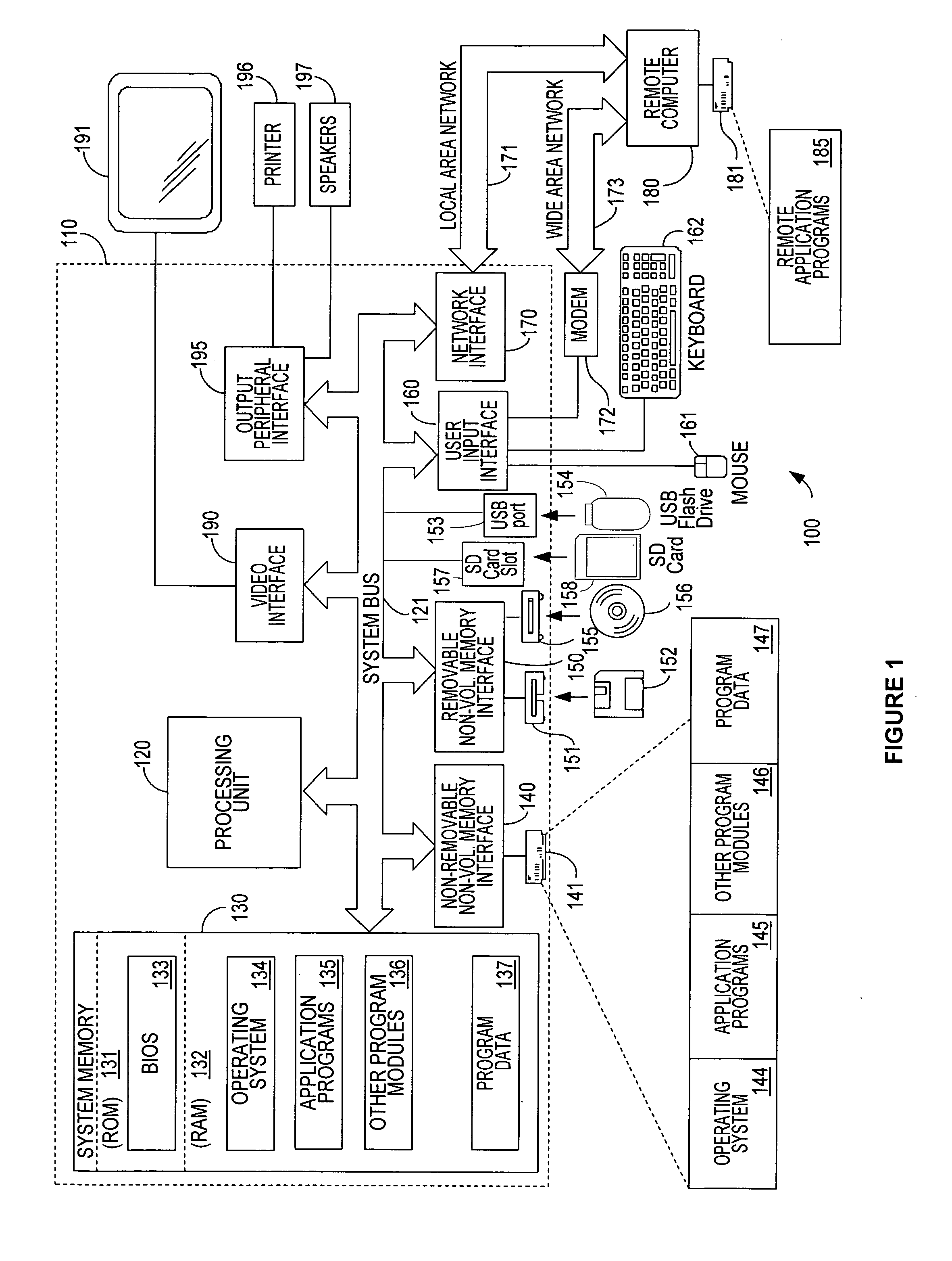
[0013] Embodiments of the invention are illustrated as being implemented in a suitable computing environment. Although not required, the invention is described in the general context of computer-executable instructions, such as procedures, being executed by a personal computer. Generally, procedures include program modules, routines, functions, programs, objects, components, data struct...


PUM


Abstract

A new system and method of available bandwidth estimation applies even where the narrow link and tight link in a network path are in different locations. In embodiments of the invention, a unique packet probe series structure and processing is employed to estimate available bandwidth. In an embodiment of the invention, the spacing between probe packets is adjusted at the source to account for dilation caused by links leading to the tight link, so that the spacing is appropriate when the probes arrive at the tight link. Moreover, the multi-packet probe comprises a large packet followed by two much smaller packets. The large packet is then dropped once it has traversed the tight link. The two small packets, which are impacted little by subsequent narrow links, preserve the spacing set by the tight link, encoding the delay induced by the tight link, all the way to the destination.

Description

FIELD OF THE INVENTION [0001] This invention pertains generally to computer networking and, more particularly, to a method and system of estimating bandwidth over a network path having different tight and narrow links. BACKGROUND OF THE INVENTION [0002] In a networking environment it is often important for entities involved in networking tasks to be able to estimate how much bandwidth is or could be available for a particular use. For example, if insufficient bandwidth is available, then it may not make sense to start a task that would have to be performed inadequately or later aborted. Often the streaming transmission of audio and video information requires a certain quality of service in order to provide a satisfactory user experience, and if that quality of service is not available then the user experience will be lacking. [0003] Recent years have seen an increase in the popularity of networking technologies, and hence an increase in techniques intended to determine available ban...

Claims


Application Information

Patent Timeline
Patent Type & Authority Applications(United States)
IPC IPC(8): H04L1/00
CPCH04L43/0858H04L43/0882H04L43/12
Inventor PADHYE, JITENDRA D.PADMANABHAN, VENKATA N.
Owner MICROSOFT TECH LICENSING LLC
Why Eureka
Try Eureka