Rotor blade for a wind power plant

a technology for wind power plants and rotor blades, which is applied in the direction of liquid fuel engines, vessel construction, marine propulsion, etc., can solve the problems of time delay and the detachment of the trailer edge, and achieve the effect of reducing the sound emission level of wind power plants

Inactive Publication Date: 2006-09-28
WOBBEN ALOYS
View PDF20 Cites 69 Cited by
  • Summary
  • Abstract
  • Description
  • Claims
  • Application Information

AI Technical Summary

Benefits of technology

The objective of this patent is to minimize the noise levels of wind power plants.

Problems solved by technology

The technical problem addressed in this patent text is the noise emitted from wind power plants, particularly from the rotor blade tips, and the impact of this noise on the acceptance of wind power plants in residential areas. The patent describes various solutions to reduce the noise levels, including the use of curved rotor blade tips and elliptical tip configurations.

Method used


Image

  • Rotor blade for a wind power plant
  • Rotor blade for a wind power plant
  • Rotor blade for a wind power plant

Examples


Embodiment Construction

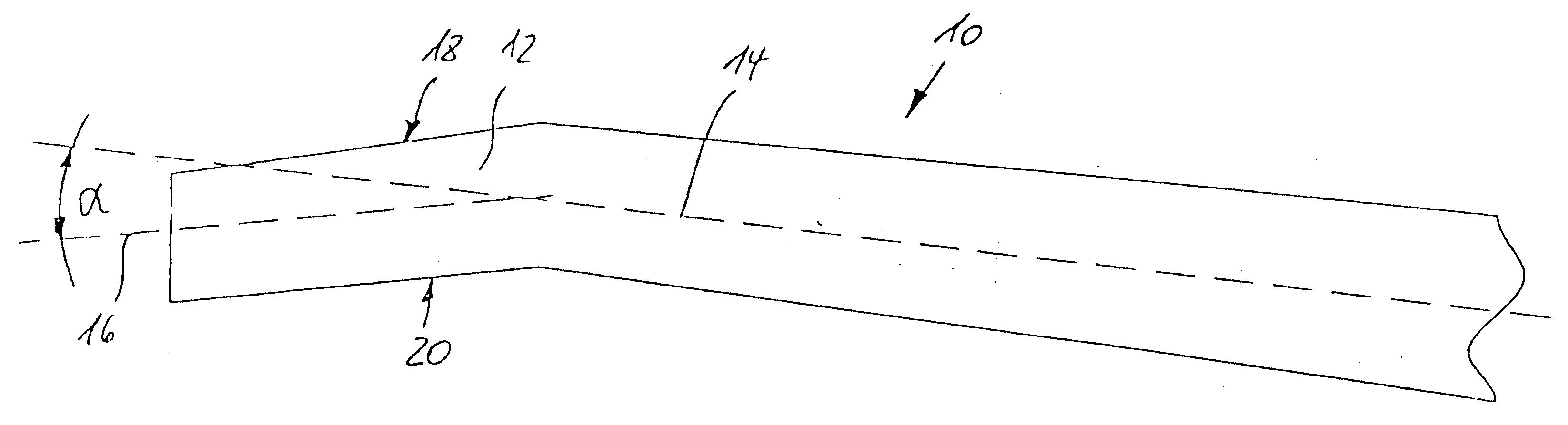
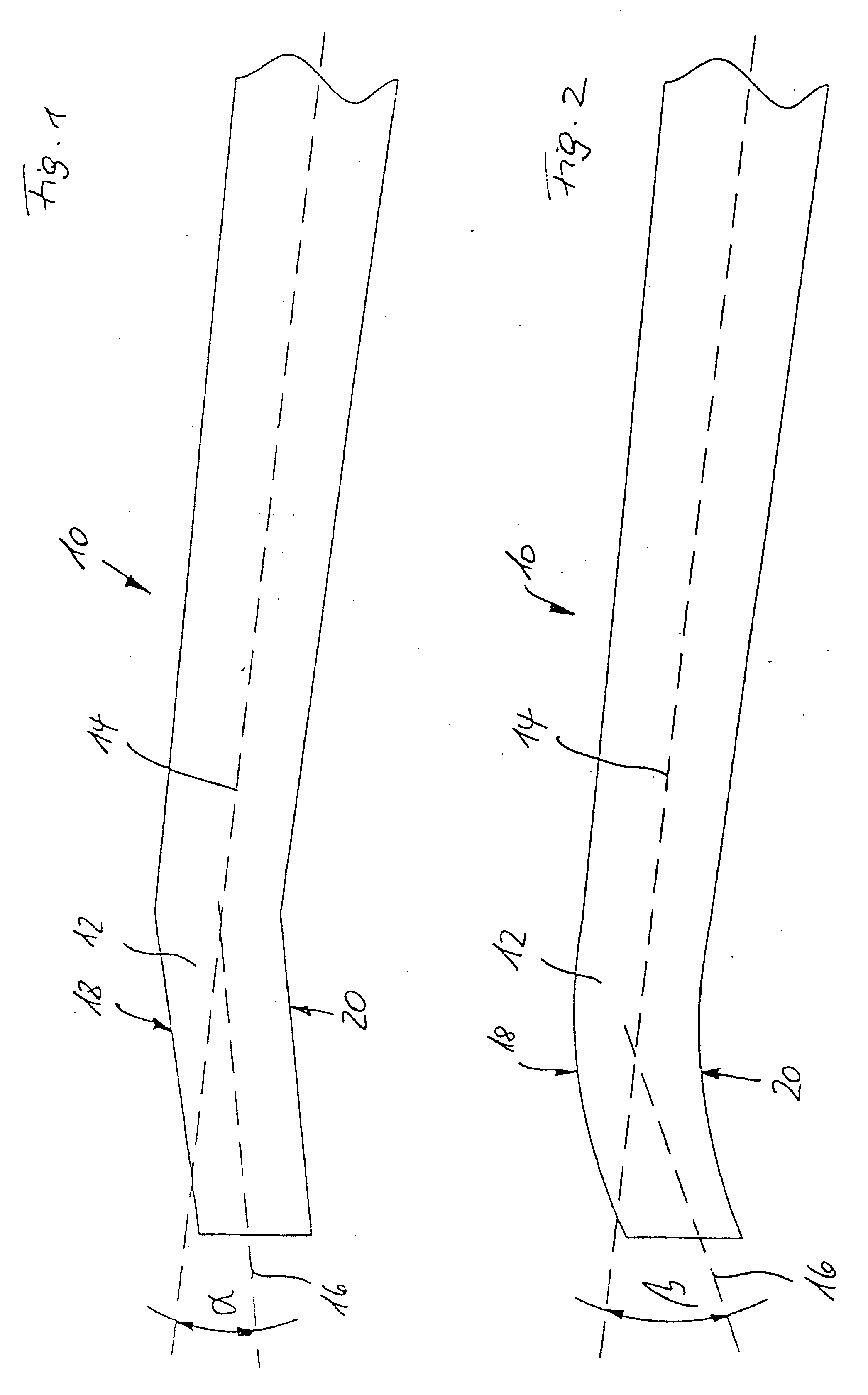
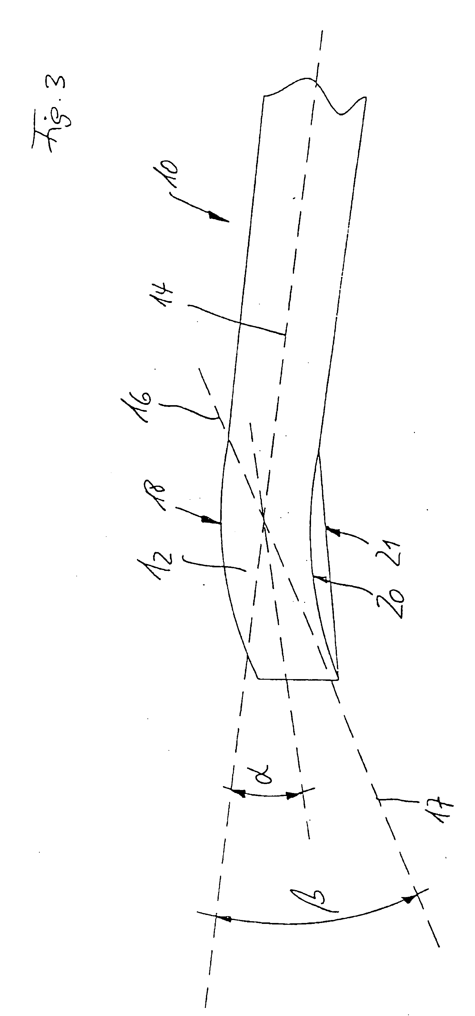
[0035]FIG. 1 shows a rotor blade 10 having a leading edge 18 and a trailing edge 20 according to the invention of a wind power plant. The thread axis 14 is indicated in the rotor blade 10. The thread axis 14 is a notional axis on to which all parts of a rotor blade are to be threaded so as to afford the desired rotor blade shape.

[0036] The end region 12 of the rotor blade 10 is bent at a predetermined angle α with respect to a first thread axis 14. A second thread axis 16 is illustrated for the end region 12, the angle α being specified between the two axes 14, 16. In this Figure the angle α is 5 degrees. That value represents an acceptable compromise between reduced sound emission and increased loading.

[0037] Therefore the end region is bent in the rotor blade plane in the direction of the rotor blade trailing edge 20. That bend results on the one hand in a longer trailing edge and thus a wider distribution of the vortex energy. On the other hand the flow breaks away at the trail...


PUM


Abstract

The present invention concerns a rotor blade for a wind power plant having an aerodynamic profile comprising a rotor blade leading edge and a rotor blade trailing edge. The invention also concerns a rotor blade tip for a rotor blade having an aerodynamic profile with a pressure and a suction side, wherein the rotor blade tip is curved or angled in its end region in the direction of the pressure side of the rotor blade. In order further to reduce the levels of sound emission of wind power plants the rotor blade is curved or angled in its edge region in the direction of the trailing edge of the rotor blade in the plane of the rotor blade. In that respect the invention is based on the realization that, in the case of a rotor blade which does not go to a point at the tip, the effective rotor blade area is maintained unreduced precisely in the outer region in which the effect is greatest. The curve or angling of the end region of the rotor blade however provides that the trailing edge is displaced rearwardly in the end region of the rotor blade so that the flow at the rotor blade trailing edge is detached with a time delay in the outer region. Alternatively to attain the object of the invention a rotor blade can be developed in such a way that the ‘outer region’ narrows. That configuration of the rotor blade tip is based on the realization that the decreasing blade depth results in a reduced flow around the blade tip as the energy thereof is previously distributed to the trailing edge vortices but at the same time the effective rotor blade area is also reduced. The angling of the rotor blade tip provides that the effective rotor blade depth remains at its optimum as far as the angled rotor blade tip.

Description


Claims


Application Information

Patent Timeline
Owner WOBBEN ALOYS
Why Eureka
Try Eureka