Methods for controlling formation of deposits in a deposition system and deposition methods including the same

a technology of deposition system and deposit method, which is applied in the direction of chemical vapor deposition coating, metal material coating process, coating, etc., can solve the problems of affecting the growth of the layer on the substrate, and reducing the quality of the formed layer

Inactive Publication Date: 2006-09-28
CREE INC
View PDF29 Cites 265 Cited by
  • Summary
  • Abstract
  • Description
  • Claims
  • Application Information

AI Technical Summary

Benefits of technology

[0006] According to embodiments of the present invention, parasitic deposits are controlled in a deposition system for depositing a film on a substrate, the deposition system of the type defining a reaction chamber for receiving the substrate and including a process gas in the reaction chamber and an interior surface contiguous with the reaction chamber. Such control is provided by flowing a buffer gas to form a gas barrier layer between the interior surface and at least a portion of the process gas such that the gas barrier layer inhibits contact between the interior surface and components of the process gas.
[0007] According to further embodiments of the present invention, a deposition system for depositing a film on a substrate using a process gas includes a reaction chamber adapted to receive the substrate and the process gas. The system further includes an interior surface contiguous with the reaction chamber. A buffer gas supply system is adapted to supply a flow of a buffer gas between the interior surface and at least a portion of the process gas such that the flow of the buffer gas forms a gas barrier layer to inhibit contact between the interior surface and components of the process gas when the process gas is disposed in the reaction chamber.
[0008] According to yet further embodiments of the present invention, a deposition control system is provided for controlling parasitic deposits in a deposition system for depositing a film on a substrate, the deposition system of the type defining a reaction chamber for holding the substrate and including a process gas in the reaction chamber and an interior surface contiguous with the reaction chamber. The deposition control system includes a buffer gas supply system adapted to provide a flow of a buffer gas between the interior surface and at least a portion of the process gas such that the flow of the buffer gas forms a gas barrier layer to inhibit contact between the interior surface and components of the process gas.
[0009] According to further embodiments of the present invention, a deposition system for depositing a film on a substrate includes a reaction chamber adapted to receive the substrate and an interior surface contiguous with the reaction chamber. A process gas is disposed within the reaction chamber. A flow of a buffer gas is disposed between the interior surface and at least a portion of the process gas. The flow of the buffer gas forms a gas barrier layer to inhibit contact between the interior surface and components of the process gas.
[0010] According to further embodiments of the present invention, a susceptor assembly for depositing a film on a substrate using a process gas and a buffer gas each flowed in a flow direction includes at least one susceptor member. The at least one susceptor member defines a reaction chamber, a process gas inlet and a buffer gas inlet. The reaction chamber is adapted to receive the substrate and has a buffer gas region to receive the buffer gas. The reaction chamber has a first cross-sectional area perpendicular to the flow direction. The process gas inlet has a second cross-sectional area perpendicular to the flow direction. The second cross-sectional area is less than the first cross-sectional area. The buffer gas inlet is adjacent the process gas inlet and is adapted to direct the buffer gas into the buffer gas region of the reaction chamber.

Problems solved by technology

Undesirably, the reagents or reactants may tend to deposit on interior surfaces of the reaction chamber as well.
The parasitic deposits on the ceiling 46 may be particularly harmful because they may dislodge and fall onto the substrate 20 during processing, reducing the quality of the formed layer.
Moreover, the changing amount of the parasitic deposits may introduce undesirable variations in temperature and gas flow dynamics, thereby influencing the growth of the layer on the substrate 20.
Depletion of the process gas because of the formation of the parasitic deposits may tend to waste reactants, thereby reducing efficiency and growth rate.
The cumulative growth time may be limited to reduce the impact of parasitic deposits on product material.
This procedure may limit both the possible length of any single growth run and the number of runs of shorter duration between cleaning cycles.
Despite such efforts, parasitic deposits may nonetheless negatively impact product material due to particle formation, process variability and reduced reactant utilization efficiency.

Method used


Image

  • Methods for controlling formation of deposits in a deposition system and deposition methods including the same
  • Methods for controlling formation of deposits in a deposition system and deposition methods including the same
  • Methods for controlling formation of deposits in a deposition system and deposition methods including the same

Examples


Embodiment Construction

[0016] The present invention now will be described more fully hereinafter with reference to the accompanying drawings, in which embodiments of the invention are shown. This invention may, however, be embodied in many different forms and should not be construed as limited to the embodiments set forth herein. Rather, these embodiments are provided so that this disclosure will be thorough and complete, and will fully convey the scope of the invention to those skilled in the art. In the drawings, the relative sizes of regions or layers may be exaggerated for clarity. It will be understood that when an element such as a layer, region or substrate is referred to as being “on” another element, it can be directly on the other element or intervening elements may also be present. In contrast, when an element is referred to as being “directly on” another element, there are no intervening elements present.

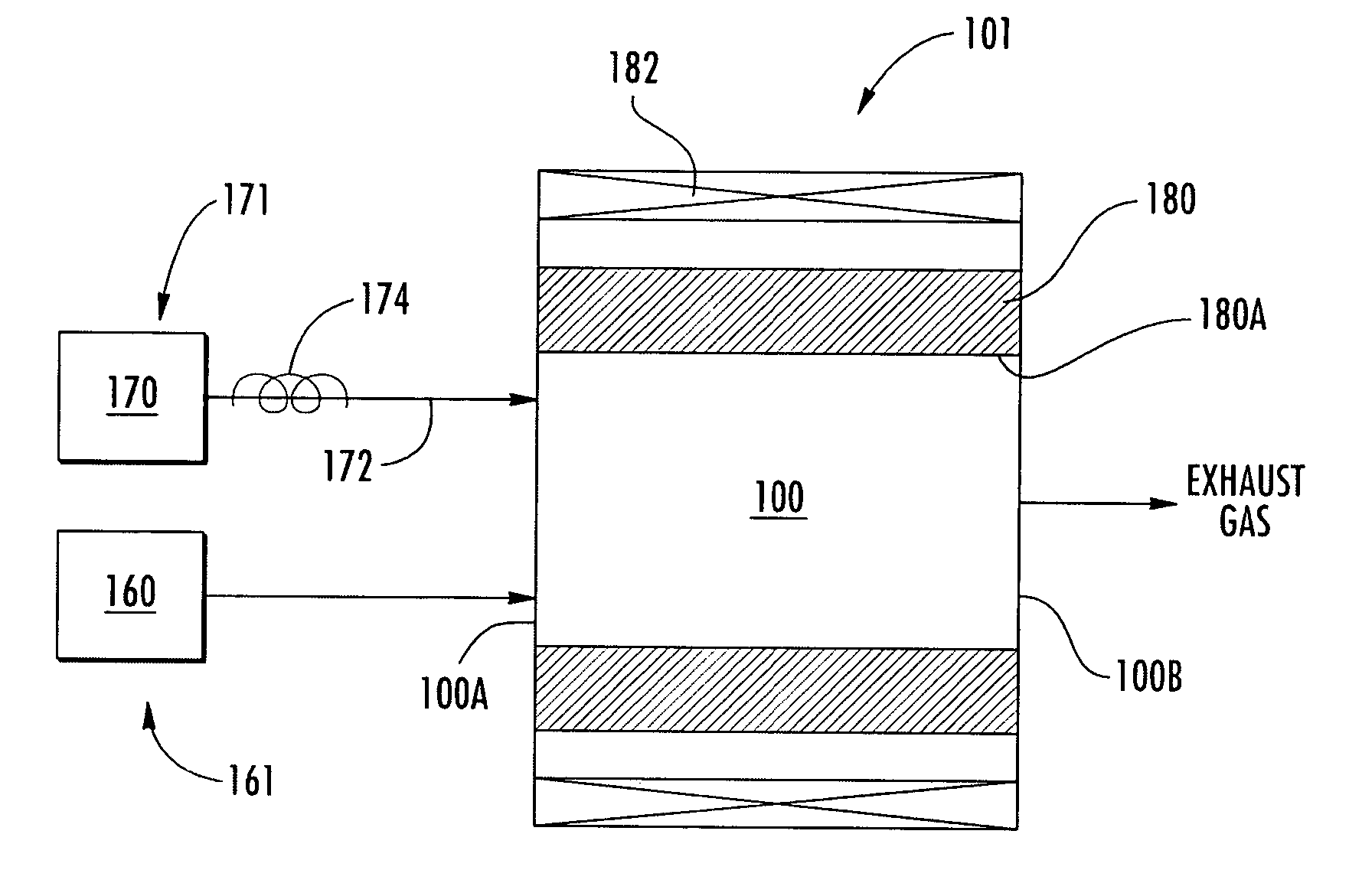
[0017] With reference to FIG. 1, a deposition system 101 according to embodiments of the ...


PUM

PropertyMeasurementUnit
velocityaaaaaaaaaa
velocityaaaaaaaaaa
velocityaaaaaaaaaa

Abstract

A method for controlling parasitic deposits in a deposition system for depositing a film on a substrate, the deposition system defining a reaction chamber for receiving the substrate and including a process gas in the reaction chamber and an interior surface contiguous with the reaction chamber, includes flowing a buffer gas between the interior surface and at least a portion of the process gas to form a gas barrier layer such that the gas barrier layer inhibits contact between the interior surface and components of the process gas.

Description

STATEMENT OF GOVERNMENT SUPPORT [0001] The present invention was made, at least in part, with government support under Office of Naval Research Contract No. N00014-02-C-0302. The United States government may have certain rights to this invention.FIELD OF THE INVENTION [0002] The present invention relates to deposition processes and apparatus and, more particularly, to methods and apparatus for depositing a film on a substrate. BACKGROUND OF THE INVENTION [0003] Deposition systems and methods are commonly used to form layers such as relatively thin films on substrates. For example, a chemical vapor deposition (CVD) reactor system and process may be used to form a layer of semiconductor material such as silicon carbide (SiC) on a substrate. CVD processes may be particularly effective for forming layers with controlled properties, thicknesses, and / or arrangements such as epitaxial layers. Typically, in a deposition system, such as a CVD system, the substrate is placed in a chamber and ...

Claims


Application Information

Patent Timeline
Patent Type & Authority Applications(United States)
IPC IPC(8): C23C16/00C23C16/44C23C16/455
CPCC23C16/4401C23C16/488C23C16/45519C23C16/455
Inventor SUMAKERIS, JOSEPH JOHNPAISLEY, MICHAEL JAMESO'LOUGHLIN, MICHAEL JOHN
Owner CREE INC
Why Eureka
Try Eureka