
Method of implanting a subcutaneous injection port having stabilizing elements

a technology of stabilizing elements and injection ports, which is applied in the field of medicine, can solve the problems of significant post-operative pain and recovery time for patients, difficult placement of bands around stomachs,

Inactive Publication Date: 2006-09-28
ETHICON ENDO SURGERY INC
View PDF16 Cites 122 Cited by
  • Summary
  • Abstract
  • Description
  • Claims
  • Application Information

AI Technical Summary

Benefits of technology

[0007] In accordance with the present invention, there is provided a method of implanting an injection port using the step of providing an injection port having a housing having a body, a fluid reservoir, a needle penetrable septum, and at least one stabilizing element mounted to the housing comprising a member having an undeployed position and a deployed position, wherein the stability element extends radially from the body. The method further involves the step of creating a surgical incision through the skin and subcutaneous fat layers of the patient to expose the fascia, and placing the injection port between the subcutaneous fat layer and the fascia tissue. The method even further involves the step of deploying the stability element.

Problems solved by technology

Placement of the band around the stomach is a difficult and important part of the surgical procedure.
In addition, suturing the injection port to tissue requires a large enough surgical incision for accessing the suturing site with dissecting instruments and needle graspers.
The associated wound and tissue trauma may result in significant post-operative pain and recovery time for the patient.

Method used


Image

  • Method of implanting a subcutaneous injection port having stabilizing elements
  • Method of implanting a subcutaneous injection port having stabilizing elements
  • Method of implanting a subcutaneous injection port having stabilizing elements

Examples


first embodiment

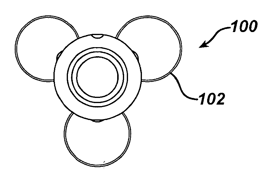
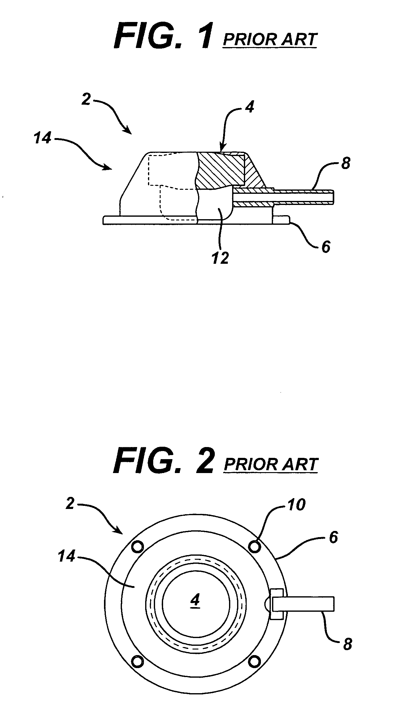
[0041]FIGS. 5, 6, 7, 8, and 9 show an injection port 100, which includes a housing 104 having a body 107 made of a rigid material such as titanium, stainless steel, or a biocompatible polymer. Housing 104 may be of a similar design as housing 14 of the prior art shown in FIG. 1, but without flange 6. A plurality of stability elements 102 attach to housing 104. Each of stability elements 102 include a member 103 that may be made of coiled, metallic wire, preferably a non-corroding, stainless steel or titanium alloy spring wire such as used for the manufacture of coiled springs. Each of stability elements 102 have a torsion spring 105 that attaches member 103 to housing 104 such that stability elements 102 tend to spring from the undeployed position to the deployed position when not sufficiently restrained. FIG. 5 is a side view and FIG. 6 is a top view of injection port 100 while stability elements 102 are in a deployed position. FIG. 7 is a side view and FIG. 8 is a bottom view of i...

second embodiment

[0043]FIGS. 10, 11, 12, 13, and 14 show an injection port 200. FIG. 10 is a side view, and FIG. 11 is a top view of injection port 200 while in a deployed position. FIG. 12 is a side view, and FIG. 13 is a top view of injection port 200 while in an undeployed position. FIG. 14 is an exploded, perspective view of injection port 200, including a plurality of stability elements 202 made of a metallic wire. Each of stability elements 202 may have a pair of ends 208 that pivotally attach to a housing 204 in holes 210. A septum 206 assembles into housing 204 in a similar manner as shown in FIG. 1 of the prior art. In this embodiment, each of stability elements 202 may be D-shaped. Initially, the surgeon may hold housing 204 with a grasper or gloved hand while injection port 202 may be in the undeployed position. As the surgeon pushes injection port 200 into the tissue of the patient, stability elements 202 unfold into the deployed position while simultaneously penetrating into tissue. The...

third embodiment

[0044]FIGS. 15, 16, 17, 18, and 19 show an injection port 300. FIG. 15 is a side view, and FIG. 16 is a top view, of injection port 300 while in a deployed position. FIG. 17 is a top view, and FIG. 18 is a side view of injection port 300 while in an undeployed position. FIG. 19 is an exploded, perspective view of injection port 300, including a plurality of stability elements 302 that are made of a spring metal wire. Each of stability elements 302 may have a D-shape as in the previous embodiment, but may be also formed to have torsion springs 314 that attach to a housing 304 with-a pin 312 into holes 310 so that stability element 302 may be in the deployed position when unrestrained. The surgeon may place injection port 302 into the tissue of a patient in a similar manner as described for injection port 200 of FIG. 14. A septum 306 assembles into housing 304 as described for the prior art of FIG. 1.


PUM


Abstract

A method of implanting an injection port using the step of providing an injection port having a housing having a body, a fluid reservoir, a needle penetrable septum, and at least one stabilizing element mounted to the housing comprising a member having an undeployed position and a deployed position, wherein the stability element extends radially from the body. The method further involves the step of creating a surgical incision through the skin and subcutaneous fat layers of the patient to expose the fascia, and placing the injection port between the subcutaneous fat layer and the fascia tissue. The method even further involves the step of deploying the stability element.

Description

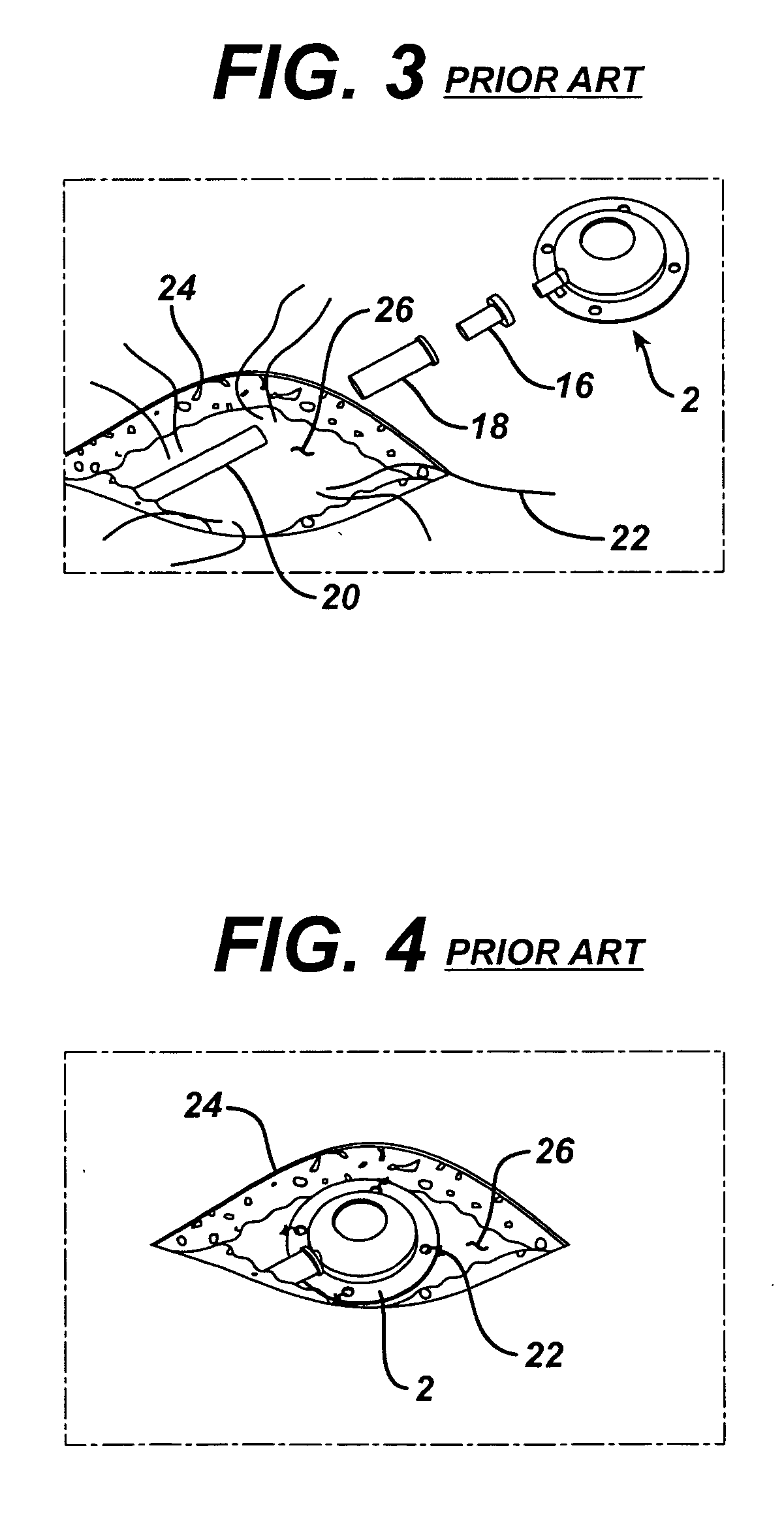
FIELD OF THE INVENTION [0001] This invention relates generally to the field of medicine, and more specifically to medical devices that are surgically implanted in a patient, and is particularly relevant to implantable injection or infusion ports such as used for chemotherapy and adjustable gastric band procedures. BACKGROUND OF THE INVENTION [0002] Surgeons routinely implant subcutaneous injection ports in patients requiring periodic fluid injections such as for chemotherapy and gastric band adjustments. The injection port connects to a flexible tube catheter to transport the fluid to the affected area (subclavian vein, etc.) or the gastric band. Current injection ports comprise a rigid metal or plastic housing, which is about 25 mm in diameter and 15 mm tall. A thick, silicone septum captured within the rigid housing covers an inner chamber that fluidly communicates with the catheter. The surgeon uses a hypodermic needle to inject fluid into the chamber through the silicone septum....

Claims


Application Information

Patent Timeline
Patent Type & Authority Applications(United States)
IPC IPC(8): A61M5/32
CPCA61M39/0208A61M39/04A61M2039/0223A61M2039/0232
Inventor SCHULZE, DALE R.CHEN, HOW-LUN
Owner ETHICON ENDO SURGERY INC
Learn More