Refrigerating device and refrigerator

a refrigerating device and refrigerator technology, applied in refrigerators/freezers, domestic cooling devices, lighting and heating devices, etc., can solve the problems of unstable refrigerant in a refrigeration cycle, increased power consumption and refrigerating device operation noise, and inability to condense refrigerant in the radiator, etc., to achieve efficient refrigerant recovery operation

Inactive Publication Date: 2006-10-05
SANYO ELECTRIC CO LTD
View PDF0 Cites 19 Cited by
  • Summary
  • Abstract
  • Description
  • Claims
  • Application Information

AI Technical Summary

Benefits of technology

[0005] Therefore, an object of the present invention is to provide a refrigerating device capable of efficiently performing a refrigerant recovering operation even in

Problems solved by technology

Thereafter, in a case where the refrigerating operation is performed, there is a problem that an amount of the refrigerant in a refrigeration cycle becomes unstable.
However, the above-described conventional refrigerating device has a problem that during the refrigerant recovering operation, the fan for the radiator needs to be o

Method used


Image

  • Refrigerating device and refrigerator
  • Refrigerating device and refrigerator
  • Refrigerating device and refrigerator

Examples


embodiment 1

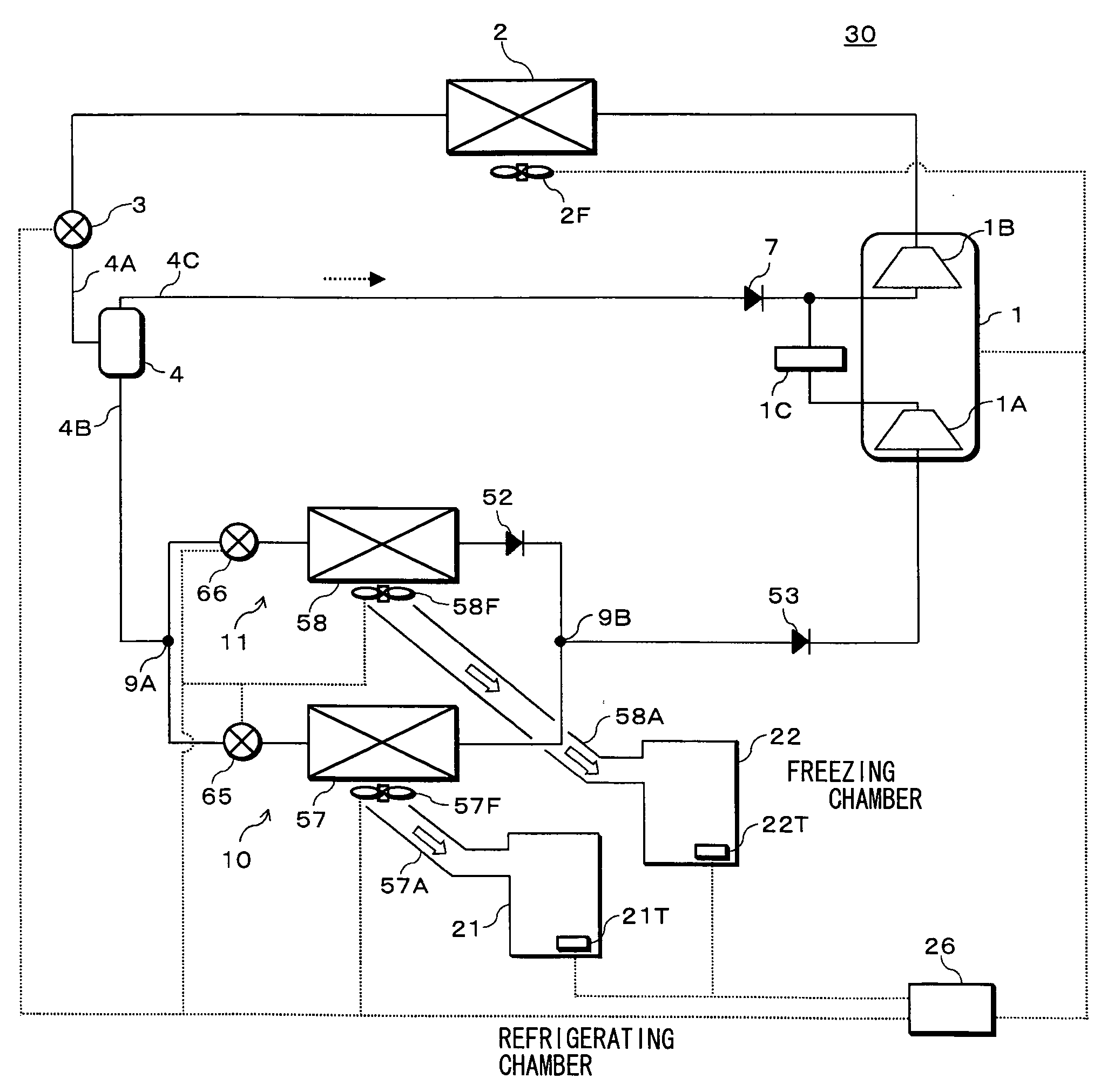
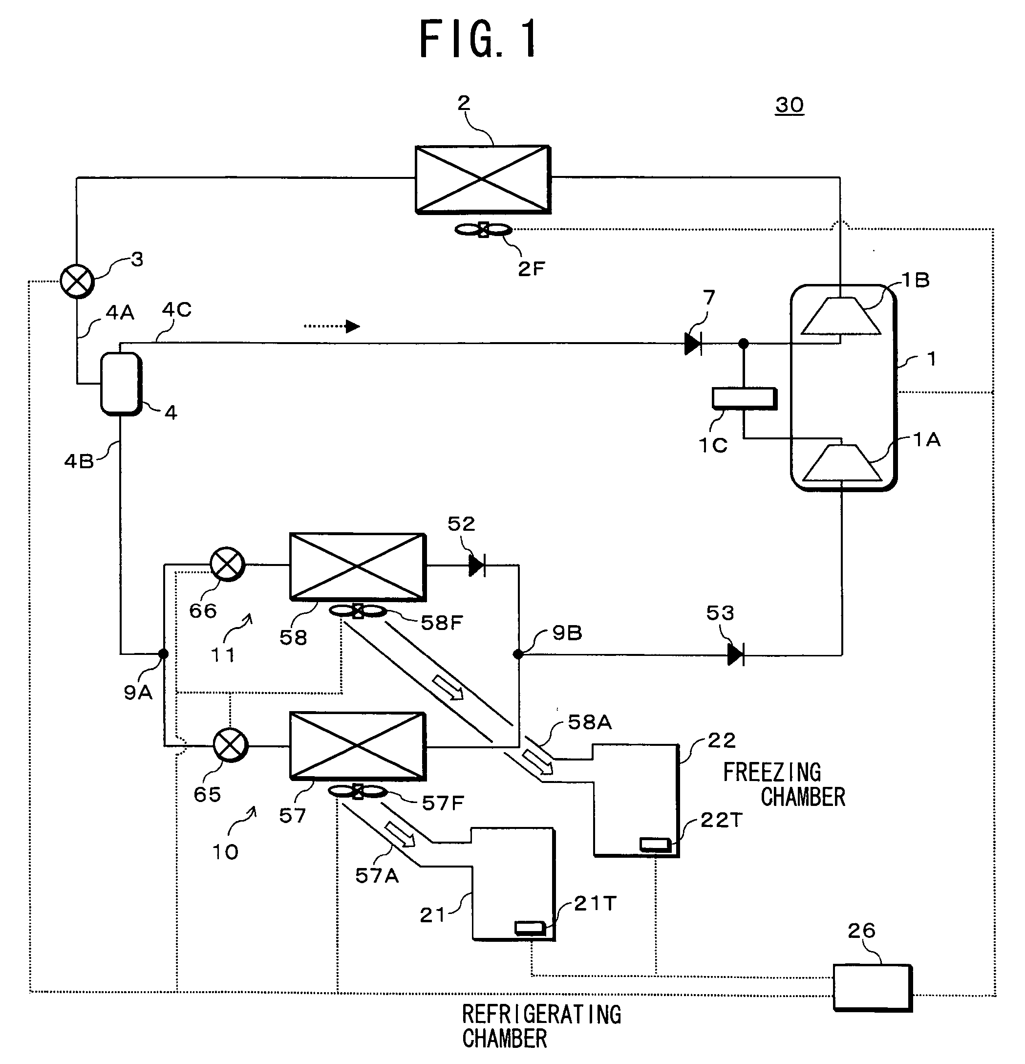
[0027] One embodiment of the present invention will be described in detail with reference to the drawings. FIG. 1 shows a refrigerant circuit diagram of a refrigerating device in one embodiment of the present invention. A refrigerating device 30 includes: a compressor 1; a radiator 2 connected to a discharge side of the compressor 1; a fan 2F which is disposed close to this radiator 2 and which cools a refrigerant in the radiator 2; an expansion valve 3 as pressure reducing means connected to an outlet side of the radiator 2; a gas-liquid separator 4 connected to a refrigerant pipe 4A on an outlet side of this expansion valve 3; a refrigerant pipe 4B in which a liquid refrigerant separated from this gas-liquid separator 4 circulates; first heat absorbing means 10 connected to one side from a branch point 9A from which this refrigerant pipe 4B is branched; and second heat absorbing means 11 connected to the other side from the branch point, disposed in parallel with the first heat ab...

embodiment 2

[0073] Next, another embodiment of the present invention will be described with reference to FIG. 7. FIG. 7 shows a refrigerant circuit diagram of a refrigerating device 50 in this case. In the present embodiment, components denoted with the same reference numerals of Embodiment 1 have identical or similar functions or effects. The present embodiment is different from Embodiment 1 in that third heat absorbing means 10B is disposed instead of the first heat absorbing means 10, and fourth heat absorbing means 11B is disposed instead of the second heat absorbing means 11.

[0074] The third heat absorbing means 10B includes a refrigerant circulation control valve 93, a capillary tube 12, and a heat sink 57. The fourth heat absorbing means 11B includes a refrigerant circulation control valve 94, a capillary tube 13 having a resistance value larger than that of the capillary tube 12, and a heat sink 58. That is, the third and fourth heat absorbing means 10B, 11B include the refrigerant cir...

embodiment 3

[0078] Next, another embodiment of the present invention will be described with reference to FIG. 8. FIG. 8 shows a refrigerant circuit diagram of a refrigerating device 70 in this case. In the present embodiment, components denoted with the same reference numerals of the above embodiments have identical or similar functions or effects. The present embodiment is different from Embodiment 1 in that the refrigerating device includes a three-way valve 91 as refrigerant channel switching means, fifth heat absorbing means 10C instead of the first heat absorbing means 10, and sixth heat absorbing means 11C instead of the second heat absorbing means 11.

[0079] The fifth heat absorbing means 10C includes a capillary tube 12 and a heat sink 57. The sixth heat absorbing means 11C includes a capillary tube 13 having a resistance value larger than that of the capillary tube 12, and a heat sink 58. That is, the fifth and sixth heat absorbing means 10C, 11C include the capillary tubes 12, 13 inst...


PUM


Abstract

There are provided a refrigerating device capable of efficiently performing a refrigerant recovering operation even in a case where there are disposed a plurality of heat absorbing units functioning in different temperature zones, and a refrigerator including this refrigerating device. A refrigerating device 30 includes a compressor 1, a radiator 2, an expansion valve 3, a gas-liquid separator 4, a first heat absorbing unit 10 through which a liquid refrigerant from this gas-liquid separator 4 flows, and a second heat absorbing unit 11, and the refrigerating device performs a refrigerant recovering operation of stopping circulation of the refrigerant into the second heat absorbing unit 11, operating the compressor 1, recovering the refrigerant stored in a heat sink 58, and sending the refrigerant to the gas-liquid separator 4 to store the refrigerant in a state in which circulation of the refrigerant into the first heat absorbing unit 10 is stopped after ending a freezing operation.

Description

BACKGROUND OF THE INVENTION [0001] The present invention relates to a refrigerating device provided with a plurality of heat absorbing means which function in different temperature zones, and a refrigerator provided with this refrigerating device. [0002] As a refrigerating device provided with a plurality of heat absorbing means which function in different temperature zones, there is known, for example, a refrigerator having: heat absorbing means for refrigerating; and heat absorbing means for freezing which functions at a temperature lower than that of the heat absorbing means for refrigerating. The respective heat absorbing means are operated to perform a freezing operation and a refrigerating operation. However, in such refrigerator, a refrigerant pools in a heat sink of the heat absorbing means for freezing, for example, during the freezing operation. Thereafter, in a case where the refrigerating operation is performed, there is a problem that an amount of the refrigerant in a r...

Claims


Application Information

Patent Timeline
IPC IPC(8): F25B41/04F25B39/02
CPCF25B1/10F25B5/02F25B9/008F25B2309/061F25B2400/13F25B2400/19Y02B40/32F25B2600/0251F25B2600/112F25B2600/2507F25B2600/2519F25D11/022Y02B30/743F25B2400/23Y02B30/70Y02B40/00
Inventor NAGAE, ETSUSHIMIZUKAMI, KAZUAKIITSUKI, HIROYUKIMUKAIYAMA, HIROSHI
Owner SANYO ELECTRIC CO LTD
Why Eureka
Try Eureka