
Waveform processing apparatus with versatile data bus

a waveform processing and data bus technology, applied in the field of waveform data processing apparatuses, can solve the problems of increasing design costs, complicated signal compositions, and difficult mass production to reduce costs, and achieve the effect of simple circuit and high versatility

Inactive Publication Date: 2006-10-05
YAMAHA CORP
View PDF14 Cites 6 Cited by
  • Summary
  • Abstract
  • Description
  • Claims
  • Application Information

AI Technical Summary

Benefits of technology

The present invention provides a waveform data processing apparatus with high versatility and a simple circuit design. The apparatus includes a bus that transfers data signals of waveform data, transmitting and receiving nodes that process the data signals, and a clock generator that generates a word clock signal per sampling period. The transmitting nodes divide the waveform data into partial data with an independent bit width for each node, and the receiving nodes selectively acquire the necessary data from the bus. The apparatus operates on the basis of an independent operation clock signal for each node, and each node generates a sync clock signal based on the operation clock signal. The apparatus can be characterized by the use of a plurality of transmitting and receiving nodes, each operating on an independent basis. The data signals can be waveform data or other types of data signals. The apparatus can be used in various applications and can provide high-speed processing of waveform data.

Problems solved by technology

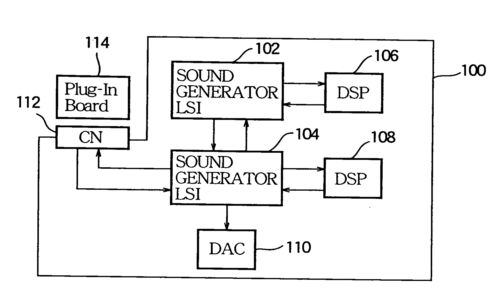
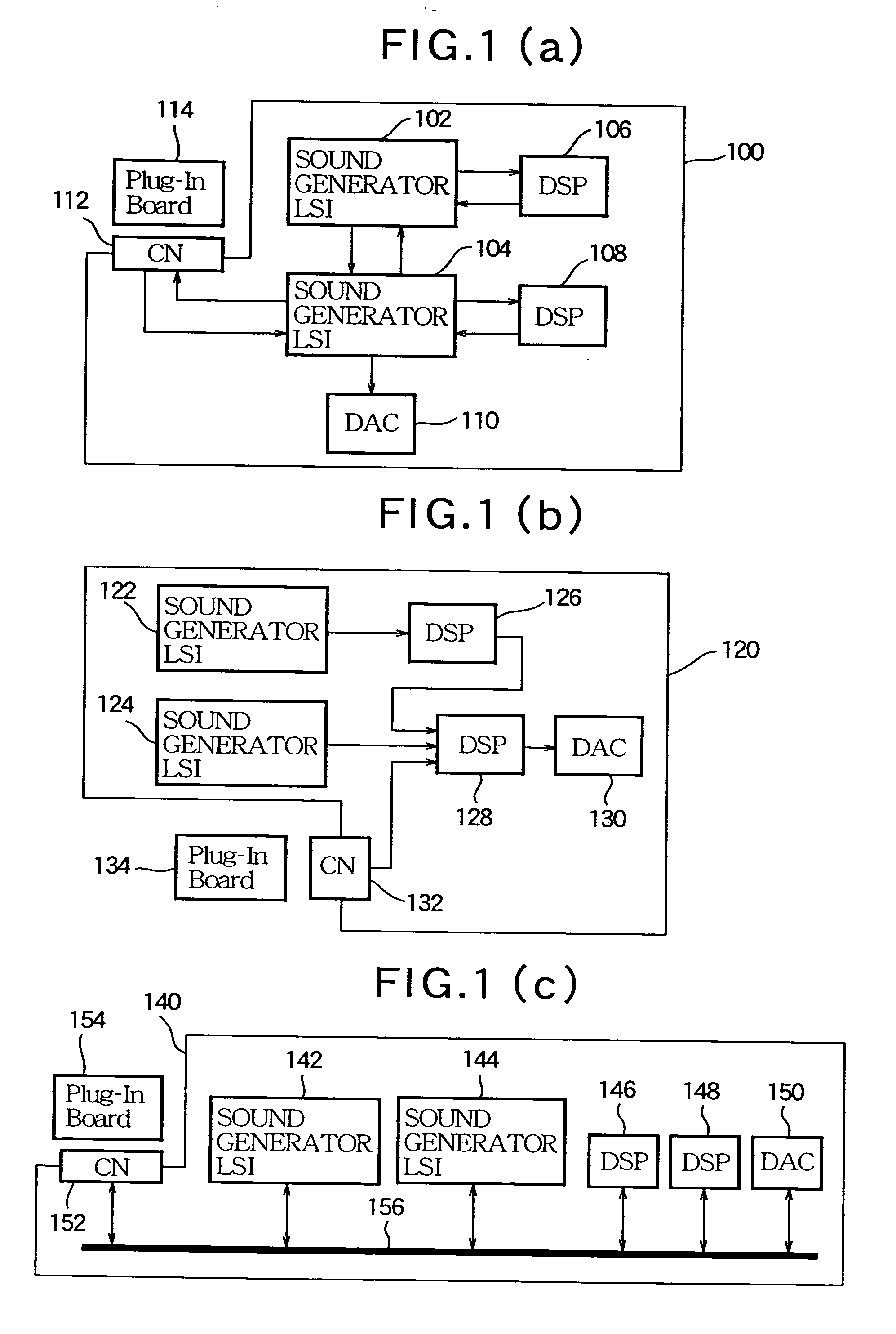
1(a) and 1(b), hardware components must be designed and produced for each kind of sound board because the sound boards 100, 120 are not compatible, thus increasing designing costs and making it difficult to lower costs by mass production.
The mLAN™ mentioned above is based on the assumption that independent equipment such as the synthesizer or digital mixer is to be the node, so that signal compositions are complicated and it is impracticable to adapt individual LSIs to the mLAN standards.
Moreover, the technique disclosed in Japanese Patent Publication Laid-open No. 5-188967 allows the specific nodes that are shown in this publication to exchange waveform data or the like, but can not be adapted to various kinds of nodes in a general and multi-purpose manner.

Method used


Image

  • Waveform processing apparatus with versatile data bus
  • Waveform processing apparatus with versatile data bus
  • Waveform processing apparatus with versatile data bus

Examples


Embodiment Construction

1. General Configuration of Embodiment

1.1. Overall Configuration

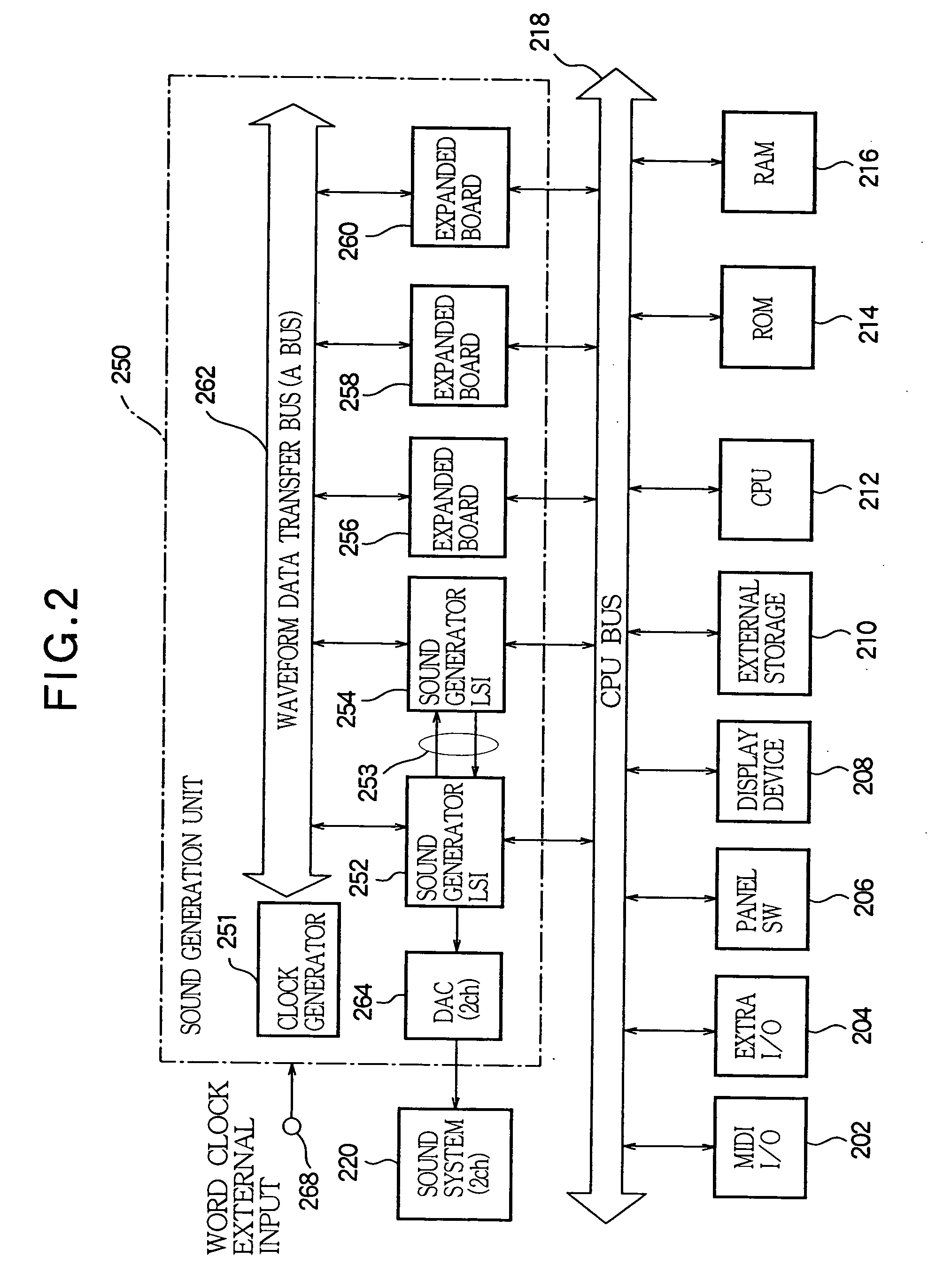
[0052] Next, a hardware configuration of a musical sound synthesizing apparatus in one embodiment of the present invention will be described in reference to FIG. 2. In the drawing, 202 denotes a MIDI•I / O section, which inputs and outputs MIDI signals from and to external MIDI equipment. A performance operation terminal such as a keyboard or the like is connected to the MIDI•I / O section 202, and performance information from the performance operation terminal is input as MIDI signals. 204 denotes an extra I / O section, which inputs and outputs various kinds of signals other than the MIDI signals. 206 denotes a panel switch section, which is provided with various kinds of tone quality setting operation terminals and the like operated by users.

[0053]250 denotes a sound generation unit, which synthesizes musical sound signals by means of processing described later. 208 denotes a display device, which displays various kin...


PUM


Abstract

A waveform data processing apparatus has a bus that transfers data signals representative of waveform data. A plurality of transmitting nodes transmit the data signals to the bus. A plurality of receiving nodes receive the data signals from the bus. A clock generator generates a word clock signal at each sampling period. A controller is responsive to the word clock signal for conducting a session of transferring the data signals within a sampling period, such that the transmitting nodes sequentially transmit the data signals in an order predetermined by the controller so as to avoid collision of the data signals within the sampling period, and each of the receiving nodes selectively admits a necessary one of the data signals outputted from the transmitting nodes and processes the admitted data signal within the sampling period.

Description

CROSS REFERENCE TO RELATED APPLICATION [0001] This application is a division of application Ser. No. 10 / 685,386 filed on Sep. 4, 2003, the entire contents of which are incorporated herein by reference.BACKGROUND OF THE INVENTION [0002] 1. Technical Field of the Invention [0003] The present invention relates to a waveform data processing apparatus with a dedicated data bus suitably used for connection among musical sound processing devices. [0004] 2. Prior Art [0005] A sound board mounted on an electronic musical instrument, personal computer or the like is equipped with a plurality of LSIs which processes musical sound signals, and these LSIs are connected by connection lines for transmitting and receiving the musical sound signals, thereby enabling necessary functions. Here, an example of the sound board mounted on the electronic musical instrument is shown in FIG. 1(a). In the drawing, 100 denotes a sound board, on which sound generator LSIs 102, 104 are mounted. The sound generat...

Claims


Application Information

Patent Timeline
Patent Type & Authority Applications(United States)
IPC IPC(8): G10H7/00
CPCG10H7/004
Inventor OKAMURA, KAZUHISA
Owner YAMAHA CORP
Learn More