Method for manufacturing tires on a flexible manufacturing system
What is Al technical title?
Al technical title is built by PatSnap Al team. It summarizes the technical point description of the patent document.
a manufacturing system and flexible technology, applied in the field of automatic tire manufacturing machines, can solve the problems of tire chafing, tire chafing, and large work area for two separate positions, and achieve the effect of preventing tire chafing
Inactive Publication Date: 2006-10-05
THE GOODYEAR TIRE & RUBBER CO
View PDF15 Cites 21 Cited by
Summary
Abstract
Description
Claims
Application Information
AI Technical Summary
This helps you quickly interpret patents by identifying the three key elements:
Problems solved by technology
Method used
Benefits of technology
[0041]“Chafer” refers to reinforcing material (rubber alone, or fabric and rubber)...
Problems solved by technology
While the two-stage building process in its separate stages accommodated servers for the various components, it presented the problems of requiring a large work area for the two separate positions and the need to coordinate the separate functions as well as bringing all of the components together at the proper stations.
As a result, the components were often stored and became subject to aging, sometimes losing their tack, for example, during the handling of the individually applied components.
Moving the tire subassemblies from one stage to another has been a highly labor intensive operation even with the use of mechanical servers to assist operators in placing the components on the tire on the first and second stage drums.
As a result, the operation was costly.
While this system, has overcome some floor space problems, its output is still limited.
Also, as disclosed in U.S. Pat. No. 1,818,955, tires can be manufactured on a line with a plurality of building drums “arranged in a train or series and a connecting means is provided for translating the cores from one device to the next.” The connectivity between the tire cores (building drums) leads to the inability to change the machine to accommodate various sized tire constructions.
Further, as disclosed in U.S. Pat. No. 5,354,404, there is illustrated another system for manufacturing tires on a line with a plurality of building drums “arranged in a train or series and a connecting means is provided for translating the cores from one device to the next.” The connectivity between the tire building cores leads to the inability to change the machine to accommodate various sized tire constructions.
The problem with these prior art manufacturing systems is tha...
Method used
Image
Click on the blue label to locate the original text in one second.
Reading with bidirectional positioning of images and text.
Examples
Embodiment Construction
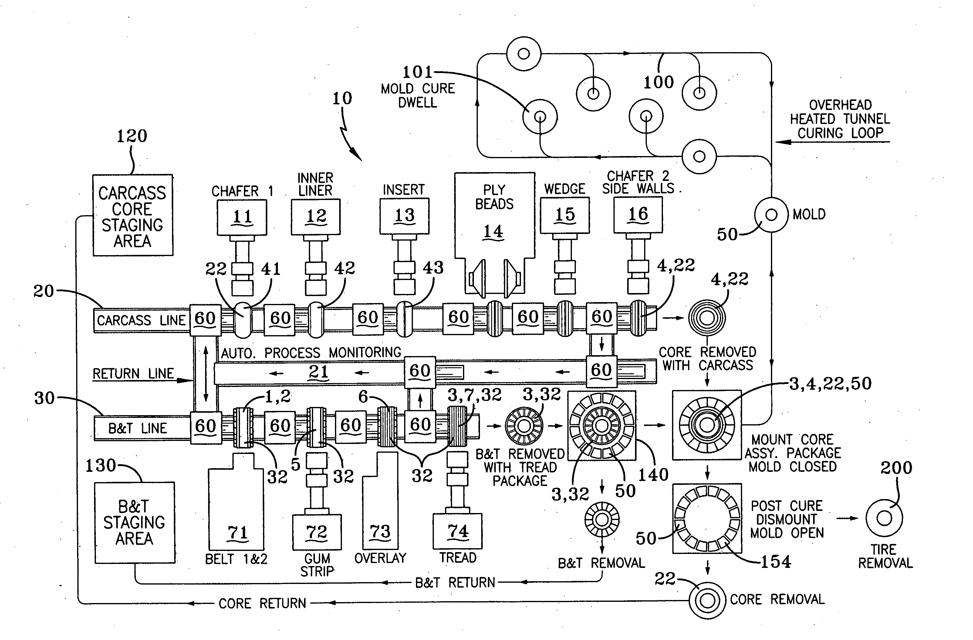
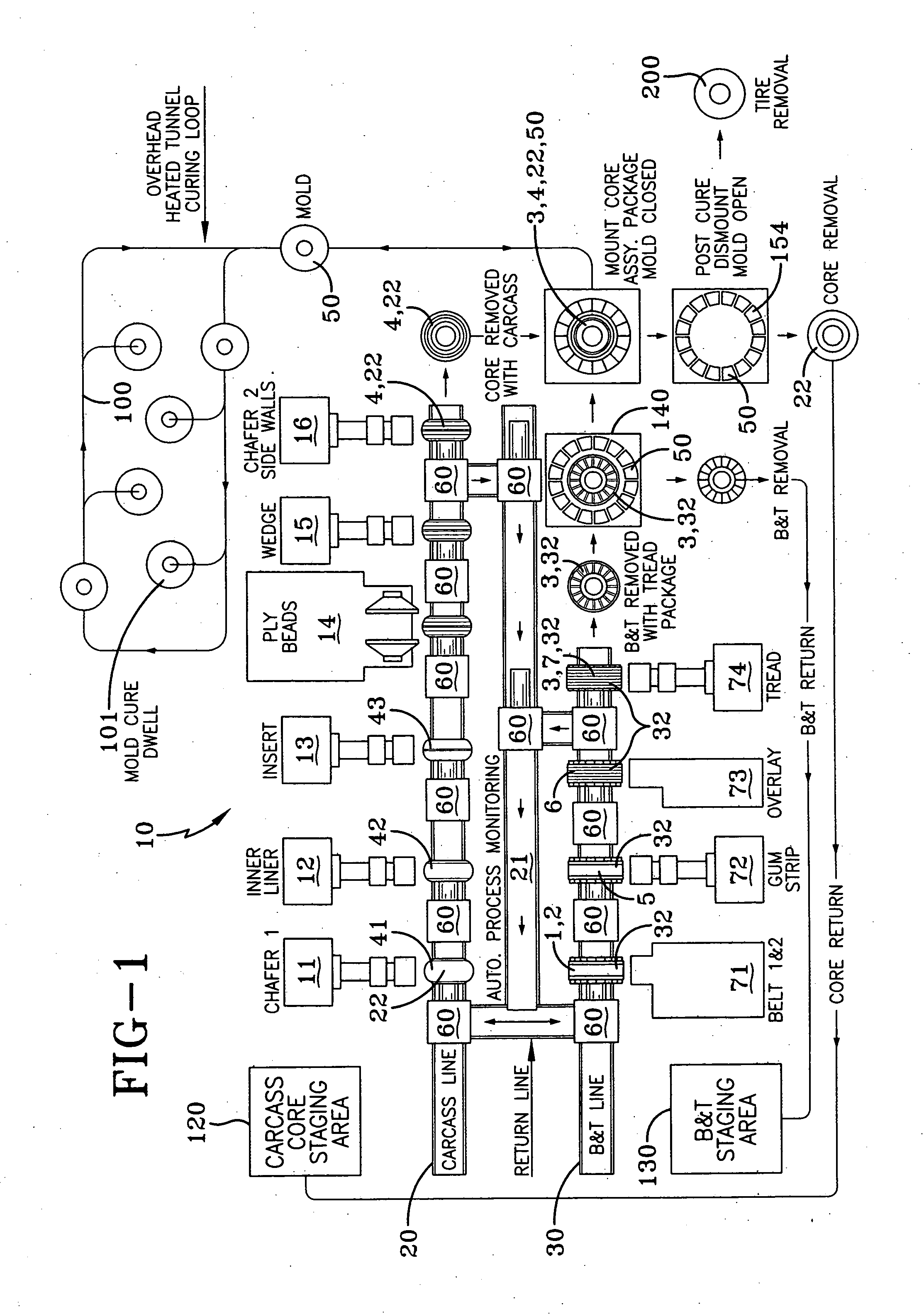
[0071] With reference to FIG. 1 a schematic view of an automated tire manufacturing system 10 according to the present invention is illustrated. This system 10 provides for the complete manufacture of pneumatic tires and provides two separate simultaneously operating first and second tire building lines, one line 20 forming the tire carcass subassembly 4, the other line 30 forming the tire belt tread subassembly 3. These two subassemblies 3, 4 will be combined into a tire curing mold 50 after their assembly is completed. When so joined at the tire building mold, the molds 50 will then be transferred into a mold curing loop 100 which permits the tires 200 to be cured, vulcanized and returned to be removed from the molds 50.
[0072] As shown the FIG. 1 at the initial building of a tire there is a carcass core staging area 120. Each core represents a specific tire building drum assembly 22 designed to permit the fabrication of the tire carcass 4 onto the toroidally expanded building dru...
PUM
Property
Measurement
Unit
Size
aaaaa
aaaaa
Flexibility
aaaaa
aaaaa
Distance
aaaaa
aaaaa
Abstract
A method of simultaneously producing production runs of tires 200 on a multi-station sequential tire manufacturing system 10, the tires 200 being from a group of tire types of different build specifications in lot sizes of one or more tires is disclosed. The steps include: scheduling the production run by imputing tire build software, wherein the software program performs the steps of: selecting the tire building equipment and materials required for the respective tire types; calculating the corresponding number of cycles each piece of building equipment must perform to build a given lot; and automatically changing to a second build specification at a lot change by switching to the second build specification after the last tire 200 of the first build specification passes; repeating the automated changing to the next build specification at each station 11-16 and 71-74) as each last tire 200 of each prior lot passes until a final lot is produced. The multi-station sequential tire manufacturing system 10 has at least four stations for carcass 4 building, each station (11-16) being spaced at a predetermined distance and preferably a multistation tread belt assembly line 30 having workstations (71-74) separate from the carcass building line 20 wherein the carcass 4 and the tread belt assemblies 3 are joined in a segmented self-locking mold 50.
Description
CROSS-REFERENCE TO RELATED APPLICATIONS [0001] This divisional patent application claims priority from co-pending U.S. patent application Ser. No. 10 / 449,468, filed May 30, 2003, currently pending. [0002] This application relates to the following U.S. patent applications entitled: “A Method and Apparatus for forming an Annular Elastomeric Tire Component”, U.S. Ser. No. 10 / 291,279, filed on Nov. 8, 2002; “An Improved Method and Apparatus for Manufacturing Carcass Plies For a Tire”, U.S. Ser. No. 10 / 365,374, filed on Feb. 11, 2003; “Radially Expansible Tire Assembly Drum and Method For Forming Tires”, Ser. No. 10 / 388,773, filed Mar. 14, 2003; “Method and Apparatus For Tread Belt Assemblies, Docket No. DN2003-078, filed on May 20, 2003; and “A Method For Curing Tires and a Self-Locking Tire Mold, U.S. Ser. No. 10 / 417,849, filed Apr. 17, 2003.FIELD OF THE INVENTION [0003] The present invention relates to automated tire manufacturing machines and, more particularly, to methods and appara...
Claims
Application Information
Patent Timeline
Application Date:The date an application was filed.
Publication Date:The date a patent or application was officially published.
First Publication Date:The earliest publication date of a patent with the same application number.
Issue Date:Publication date of the patent grant document.
PCT Entry Date:The Entry date of PCT National Phase.
Estimated Expiry Date:The statutory expiry date of a patent right according to the Patent Law, and it is the longest term of protection that the patent right can achieve without the termination of the patent right due to other reasons(Term extension factor has been taken into account ).
Invalid Date:Actual expiry date is based on effective date or publication date of legal transaction data of invalid patent.