Operation control device for saddle type motor vehicle

a technology of operation control and motor vehicle, which is applied in the direction of engine controller, cycle control system, cycle equipment, etc., can solve the problems of not easy for inexperienced riders, affecting the operation of the vehicle, and documents that do not disclose anything about controlling the driving for

Inactive Publication Date: 2006-10-05
YAMAHA MOTOR CO LTD
View PDF3 Cites 14 Cited by
  • Summary
  • Abstract
  • Description
  • Claims
  • Application Information

AI Technical Summary

Benefits of technology

[0007] In order to overcome the problems described above, preferred embodiments of the present invention provide an operation control device for a saddle type motor vehicle that can control the driving force in response to the weight shift of the rider, in addition to the operation of the throttle and the like.

Problems solved by technology

Unlike a four wheel automobile in which the driver operates the accelerator pedal with a foot to adjust the throttle opening degree, the weight shift of the rider greatly affects the operation of the vehicle.
The weight shift is easy for experienced riders, however, it is not easy for inexperienced riders.
However, these prior art documents do not disclose anything about controlling the driving force in response to the weight shift of the rider.

Method used


Image

  • Operation control device for saddle type motor vehicle
  • Operation control device for saddle type motor vehicle
  • Operation control device for saddle type motor vehicle

Examples


first preferred embodiment

Structure of the Operation Control Device

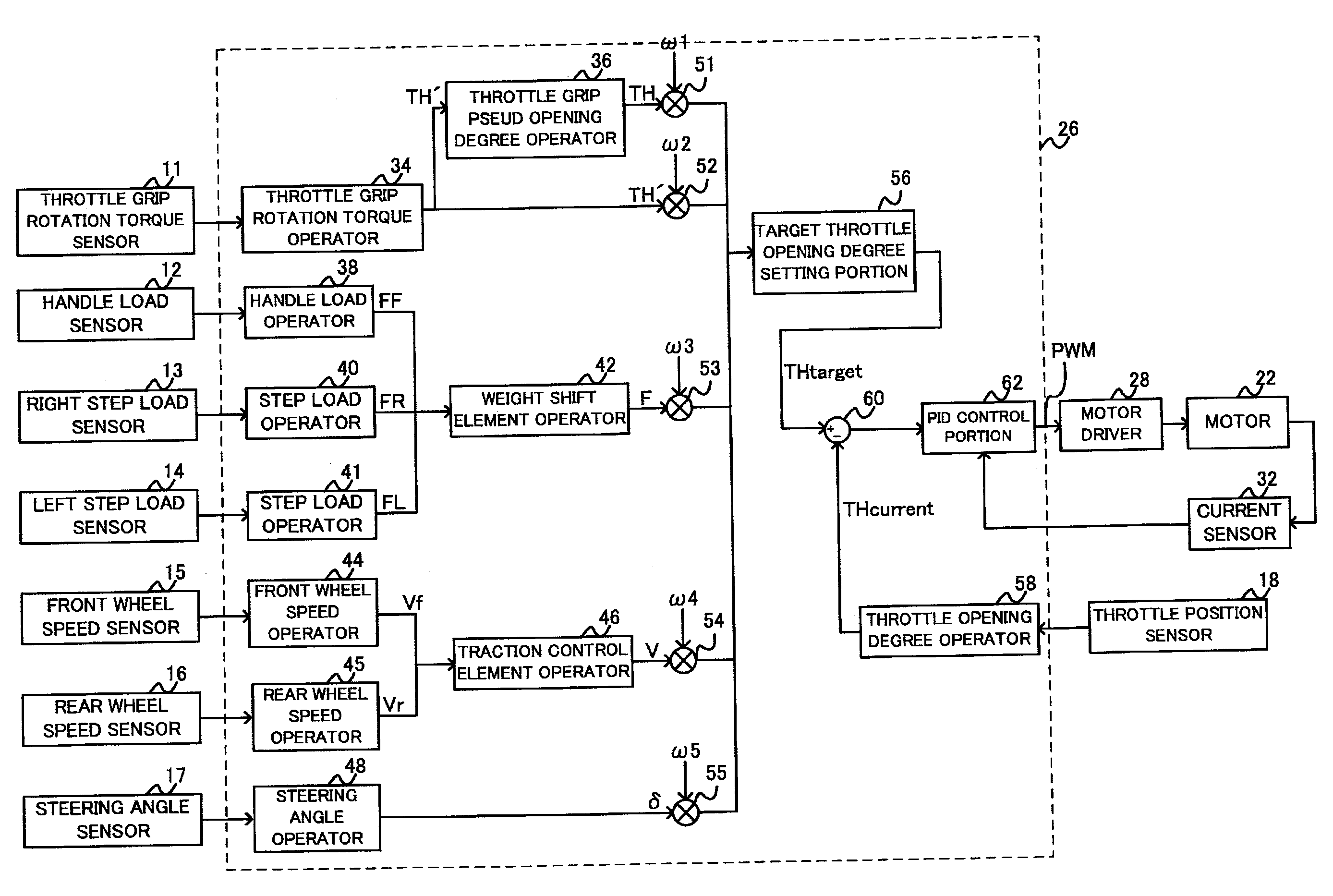
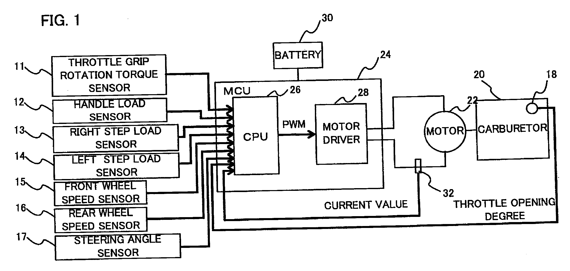
[0034] Referring to FIG. 1, an operation control device according to a first preferred embodiment of the present invention preferably includes various kinds of sensors 11 to 18 mounted to a motorcycle, an electric motor 22 that rotates the throttle valve of a carburetor 20, and an MCU (Motor Control Unit) 24 that controls the electric motor 22 in response to the output signals of the sensors 11 to 18.

[0035] The MCU 24 includes a CPU (Central Processing Unit) 26 that produces a PWM (Pulse Width Modulation) signal based on the output signals of the sensors 11 to 18, and a motor driver 28 that drives the electric motor 22 in response to the PWM signal. The MCU 24 is connected to a battery 30 and supplied with power therefrom.

[0036] A current sensor 32 inserted in an interconnection for the electric motor 22 detects the value of current passing through the electric motor 22 and feeds back the data to the CPU 26. In this way, the MCU 24 carrie...

second preferred embodiment

[0078] According to the first preferred embodiment, each element is preferably multiplied by a constant weight coefficient, although each element may be multiplied by a varying weight coefficient depending on the value of an input element. That is, a mapping operation may be carried out. In the graph in FIG. 10, the abscissa represents the value of the input element before a mapping operation and the ordinate represents the value of the output element after the mapping operation. When a constant weight coefficient is multiplied, the value of the output element is in proportion to the input element (see reference number 106 in FIG. 10). In contrast, in a mapping operation, a weight coefficient varying depending on the value of the input element is multiplied, and therefore the value of the output element is not in proportion to the input element and varies according to a predetermined function (see reference number 108 in FIG. 10). In this example, as the input element increases, the...

third preferred embodiment

[0079] The throttle grip according to the first preferred embodiment allows its torque to be detected based on even a slight amount of its rotation, and this is why the throttle grip rotation torque sensor 11, the throttle grip rotation torque operator 34, and the pseudo opening degree operator 36 are used. However, if a normal throttle grip is used, as shown in FIG. 11, a throttle grip opening degree sensor 110, a throttle grip opening degree operator 112, and a throttle grip rotation torque operator 114 may be used instead of the above-described elements.

[0080] The throttle grip opening degree sensor 110 is mounted to the throttle grip to detect the opening degree of the throttle grip. The throttle grip opening degree operator 112 calculates a throttle grip opening degree element TH (a value proportional to the opening degree of the throttle grip) based on the output signal of the throttle grip opening degree sensor 110. The throttle grip rotation torque operator 114 differentiat...


PUM


Abstract

An operation control device determines the operation of a throttle grip rotation torque element having a throttle grip rotation torque sensor and a throttle grip rotation torque operator, and a pseudo operation degree element for a throttle grip by integration using a throttle grip pseudo opening degree operator. A handle load sensor and a handle load operator detect a handle load. Right and left step load sensors and right and left step load operators detect right and left step loads. A weight shift element operator calculates a weight shift element. A target throttle opening degree is determined based on the operation of these elements, and a throttle valve is rotated by PID control. The operation control device can control a driving force in response to the weight shift of a rider in addition to the operation of the throttle grip.

Description

BACKGROUND OF THE INVENTION [0001] 1. Field of the Invention [0002] The present invention relates generally to an operation control device for a saddle type motor vehicle, and particularly to a saddle type motor vehicle such as a motorcycle, an all terrain vehicle (ATV), a snowmobile, and a hydroplane controlled by a rider shifting his weight. The present invention relates more particularly to an operation control device suitably applied to a saddle type motor vehicle, such as a motorcycle. [0003] 2. Description of the Related Art [0004] In a saddle type vehicle, the rider manually operates a throttle grip provided on a handle to adjust the throttle opening degree. Unlike a four wheel automobile in which the driver operates the accelerator pedal with a foot to adjust the throttle opening degree, the weight shift of the rider greatly affects the operation of the vehicle. [0005] For motorcycles, especially for off-road model motorcycles, the posture of the rider is crucial when the mo...

Claims


Application Information

Patent Timeline
Patent Type & Authority Applications(United States)
IPC IPC(8): B62K11/00B62J99/00
CPCB62K23/02F02D11/02F02D2200/602F02D11/105F02D11/04
Inventor WATANABE, KENICHIHARA, NOBUOIMAI, ATSUSHI
Owner YAMAHA MOTOR CO LTD
Why Eureka
Try Eureka