Vented disc brake rotor

a brake rotor and vented disc technology, applied in the direction of brake discs, slack adjusters, braking elements, etc., can solve the problems of increasing the frequency of vibration, the frequency of vibration is increasing, and the friction-induced dynamic instability is notoriously difficult to predict, so as to reduce the likelihood of brake squealing and not adversely affect the structural integrity, cooling capabilities or functional attributes.

Active Publication Date: 2006-10-05
FEDERAL MOGUL WORLD WIDE LLC
View PDF40 Cites 25 Cited by
  • Summary
  • Abstract
  • Description
  • Claims
  • Application Information

AI Technical Summary

Benefits of technology

[0013] Using the complex eigenvalue analysis method, a geometric configuration of the ventilated brake disc rotor including a pin cluster has been identified to be particularly effective in attenuating vibration modes in the objectionable, audible frequencies. The novel pin cluster configuration can be designed so as not to adversely affect the structural integrity, cooling capabilities or functional attributes of a ventilated brake disc rotor. Furthermore, the pin cluster configuration can be readily implemented with only minor alterations to existing rotor tooling. Thus, by altering the configuration of a vented disc brake rotor with the novel pin cluster, the likelihood of brake squeal is substantially reduced, thereby averting a negative consumer impression as to the quality of the vehicle and / or its braking system.

Problems solved by technology

Certain vibration modes will have a larger amplitude than others, and when the large amplitude modes occur at certain audible frequencies, in conjunction with an excitation input of like frequency, an objectionable squealing noise may be heard.
The distinctive high-pitched sound of brake squeal is a friction-induced dynamic instability that is notoriously difficult to predict.
Squeal occurs even in new vehicles when system instability causes the vibration to be self-excited, and the vibration amplitude rises increasingly higher.
Although brake squeal is not indicative of a defect in the braking system, a perception of a mechanical problem is created, or a presumption that the brake has been poorly made.
This negative consumer impression, albeit falsely based, is particularly harmful to vehicle manufacturers, dealers, and the makers of braking systems.
However, because of the numerous variables thought to contribute to brake squeal, this is a notoriously challenging endeavor.
Notwithstanding the usefulness of the complex eigenvalue method as a diagnosis tool, design engineers still do not fully understand the underlying mechanisms which cause brake squeal, and as a result continue searching for new and improved solutions that will completely, or at least substantially, eliminate the objectionable audible frequencies at the root of brake squeal.

Method used


Image

  • Vented disc brake rotor
  • Vented disc brake rotor
  • Vented disc brake rotor

Examples


Embodiment Construction

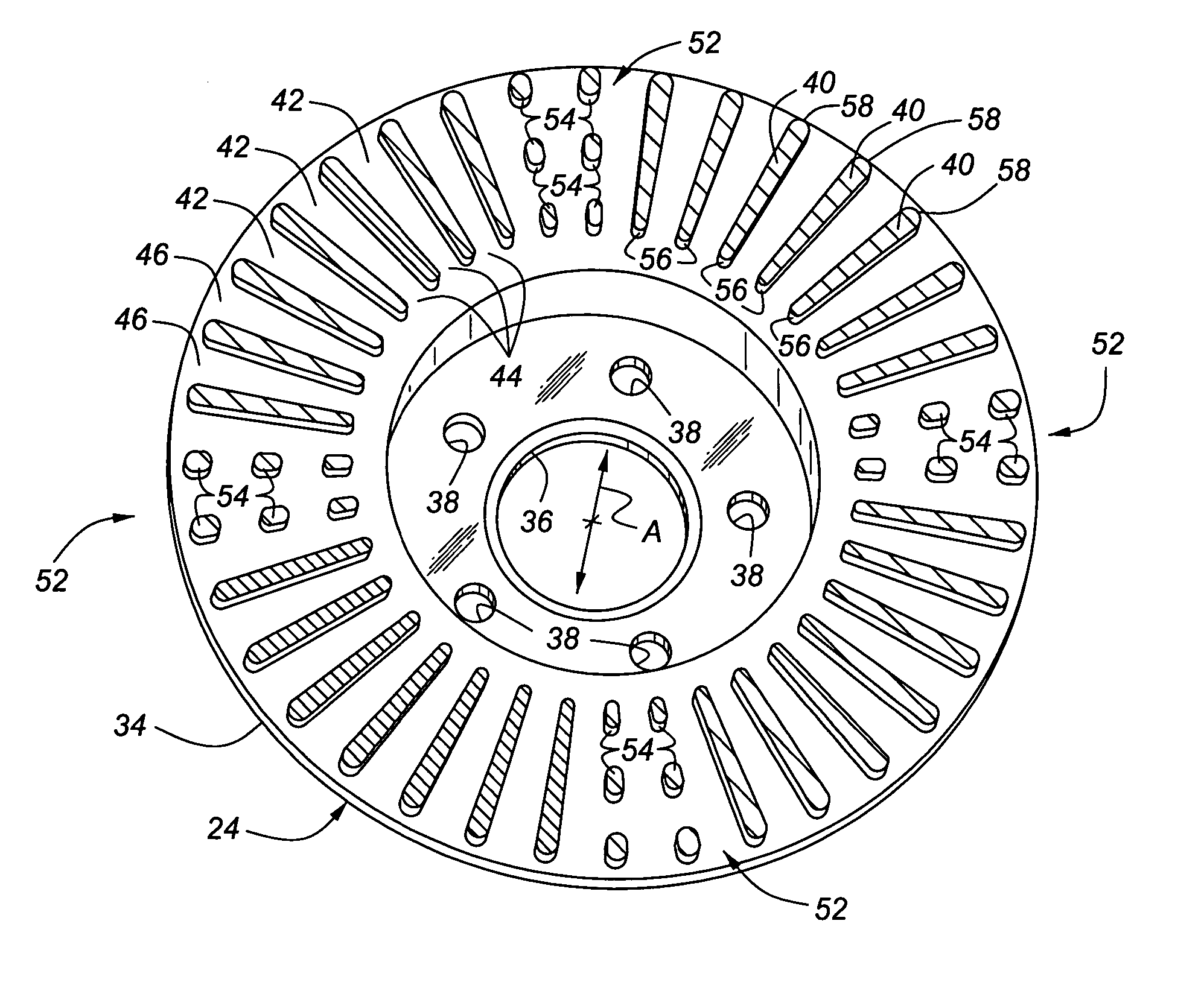
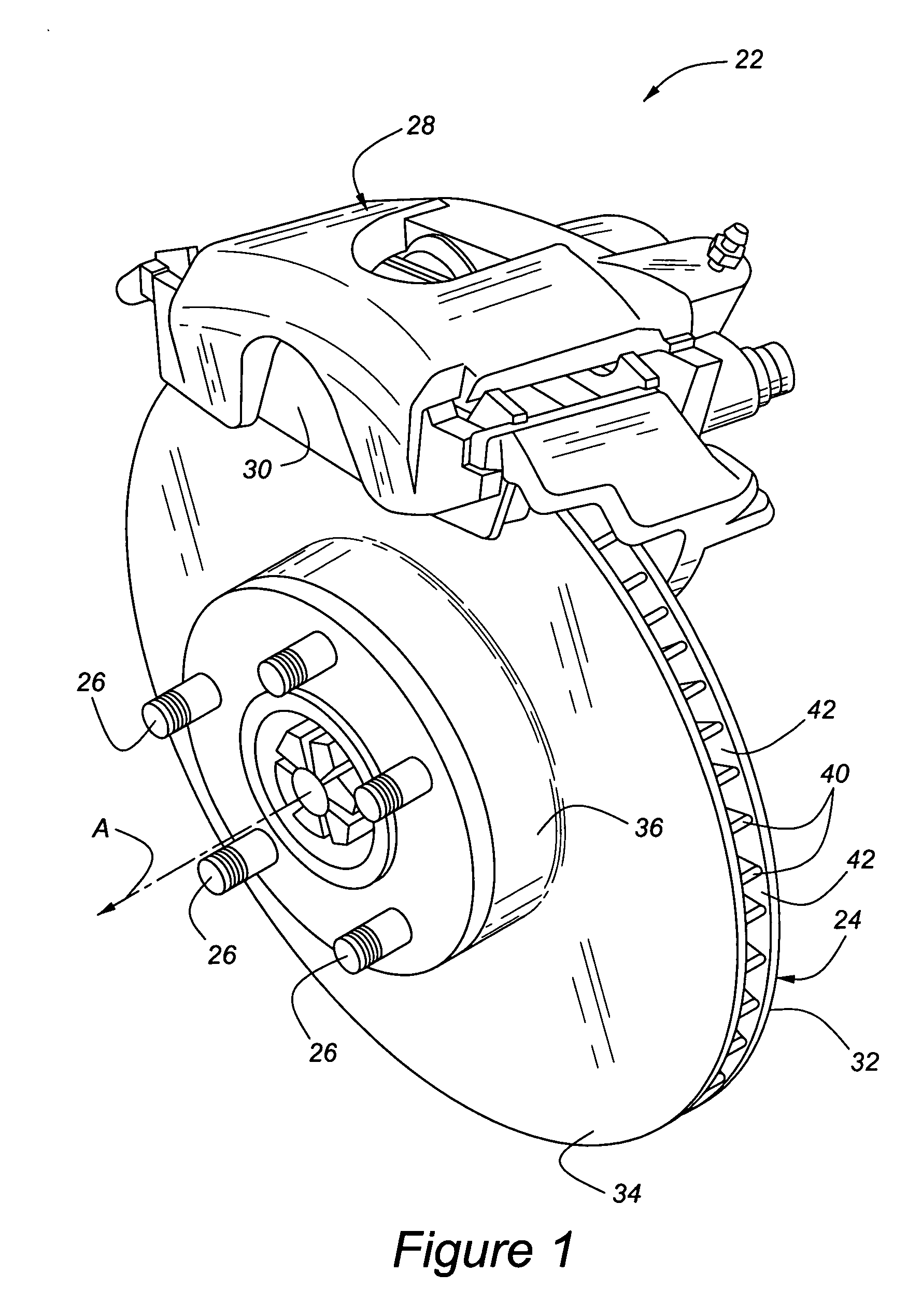
[0027] Referring to the Figures, wherein like numerals indicate like or corresponding parts throughout the several views, a disc brake rotor assembly is generally shown at 22 in FIG. 1. The assembly 22 includes a rotor, generally indicated at 24, which is connected to an axle hub via lug bolts 26. A vehicle wheel, not shown, is attached over the lug bolts 26. A caliper, generally indicated at 28, carries a pair of brake friction pads 30 on opposite sides of the rotor 24. In response to hydraulic, pneumatic, electromechanical, or other actuating means activated by the vehicle operator, the disc brake pads 30 are squeezed into clamping contact with the opposing friction surfaces of the rotor 24 to arrest rotation of the wheel.

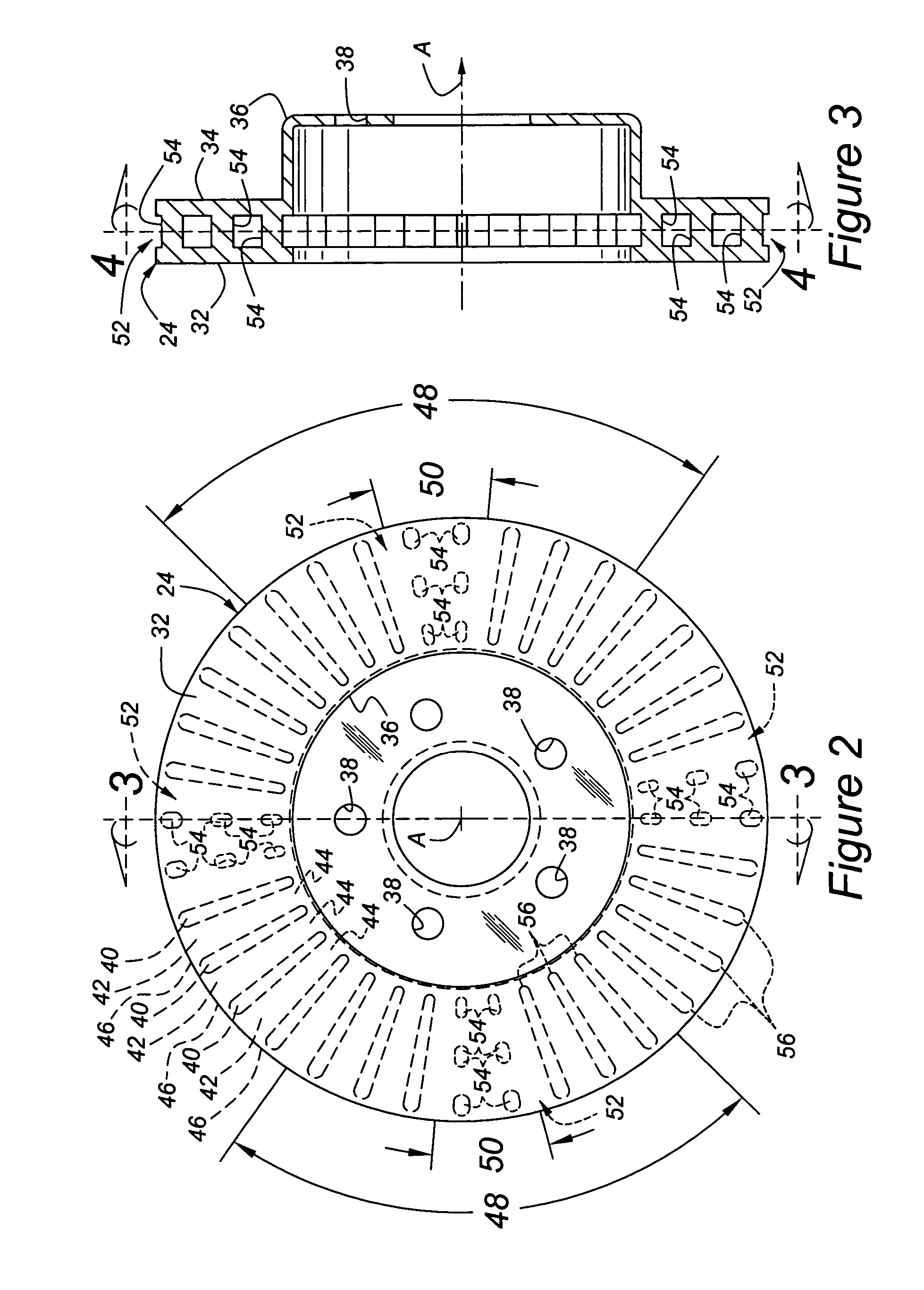
[0028] As perhaps best shown in FIGS. 2 through 4 and 7A, the rotor 24 is of the ventilated type including an annular inboard friction plate 32 which is centered about a central axis A. The central axis A is coincident with the rotational axis of the associated ...


PUM


Abstract

A brake disc assembly (22) for a vehicle includes a ventilated rotor (24) defined by vent holes (42) between inboard (32) and outboard (34) friction plates. The vent holes (42) are separated by ribs (40) spaced in regular circumferential increments about the rotor (24). The rib pattern (40) is divided into two or more sectors (48) of equal angular measure. Within each sector (48), an attenuation region (50) interrupts two or more ribs (40) by replacing the ribs (40) with a cluster of individual pins (54) which may be arranged in radial and circumferential rows. The pins (54) can have consistent circular or varying cross-sectional configurations. Each attenuation region (50) spans a territory within each sector (48) that is preferably at least 20% and less than 55% of the sector (48) real estate. The rotor (24) completely or at least substantially eliminates vibration modes in objectionable, audible frequencies without adversely affecting the structural integrity, cooling capabilities or functional attributes of the disc brake assembly (22).

Description

[0001] This application claims priority to U.S. Provisional Patent Application No. 60 / 666,667, filed Mar. 30, 2005 which is incorporated by reference herein in its entirety.BACKGROUND OF THE INVENTION [0002] 1. Field of the Invention [0003] The invention relates to a disc brake rotor, and more particularly toward a vented rotor configured to attenuate brake squeal noise. [0004] 2. Related Art [0005] A rotor for a disc brake forms part of the vehicle braking system and rotates together with a wheel. The rotor has a pair of opposed friction surfaces against which brake pads are brought into contact to arrest rotation of the wheel. In many applications, the rotor section of the disc brake is ventilated between the friction surfaces to improve cooling characteristics by dissipating heat produced from friction during the braking process. Ventilated rotors are normally arranged so that a plurality of radially extending vent holes are formed between inboard and outboard friction plates, wi...

Claims


Application Information

Patent Timeline
Patent Type & Authority Applications(United States)
IPC IPC(8): F16D65/78
CPCF16D65/12F16D2065/1328F16D65/847
Inventor LU, JIANSCHMIDT, GEORGE ROBERT
Owner FEDERAL MOGUL WORLD WIDE LLC
Why Eureka
Try Eureka