
Filter device

Inactive Publication Date: 2006-10-05
ASTRAZENECA AB
View PDF19 Cites 2 Cited by
  • Summary
  • Abstract
  • Description
  • Claims
  • Application Information

AI Technical Summary

Benefits of technology

[0012] The aim of the present invention is to provide a filter device for a fluidised bed system, especially but not exclusively for use in pharmaceutical industry, which do not have the above mentioned disadvantages. It is also an aim to provide a filter device with a separating grain that can easily be varied.
[0014] The term “separating grain” does herein refer to the size of the smallest particle that does not pass the filter device, and could be regarded as a measure of the limit of separation for said filter device. The separating grain will be determined by the mesh size of the filter portion and by the velocity of the filter portion. By varying the speed of rotation of the filter portion, the separating grain can thus be varied using only one separating system, which eliminates the need of different filters for separating particles of different sizes. Normally, the separating grain can have a range of 10-500 microns. Typically, the separating grain will be 50 microns, i.e. particles smaller than 50 microns will pass through the filter device and thus, all particles larger than 50 microns will stay in the fluidised bed system.
[0016] The housing could for example be formed like a drum, which is mounted to be rotationally movable. The filter portion is then advantageously disposed at the circumference of said drum. The drum shape has the advantage that the filter device can easily be maintained at a constant rotational speed. The centrifugal forces created also contribute to keep the filter portion clean from particles. Besides, a large active area covered with the filter portion can be used.
[0020] The filter portion may also be provided in conduits leading to or from the vessel. By providing such conduits with the filter device clogging of the conduits can be prevented.
[0022] Advantageously, the housing also comprises first and second body parts that are detachably interconnected. By separating the first and second body part, easy cleaning between batches or sterilising of the filter device is possible if necessary.
[0024] Preferably an open space is defined between the housing and the filter holder means, through which open space fluid pressure is provided, constituting a fluid seal between the housing and the filter holder means. The fluid pressure will keep the open space free from particles, and thus ensure a smooth movement of the filter device.

Problems solved by technology

If a fluid is passed upward through a bed of fine particles at a certain velocity, the frictional force between particles and fluid will just counterbalance the weight of the particles.
On the other hand if drying of the agglomerates or coatings happens too quickly, unwanted spray drying of the material might appear.
Each time a particle passes the nozzle, it will be sprayed with coating material and thus grow in size and weight.
Furthermore, the efficiency of a cyclone separator is low when separating very small particles, such as dust of spray-dried material from the coated / granulated particles.
This is time-consuming and interrupts the operation of the fluid bed apparatus.
Filtration members made by paper or textile fabric have an additional disadvantage in that they have low strength and therefore they might be damaged when cleaned or blown out.
Particles clogging in the filter structure are a problem, which gives rise to the need of cleaning the filters.
Even if cleaning sometimes can be made during operation of the process, the fluid flows will be disturbed, and the overall efficiency will be decreased.
The use of deflectors in for example a fluid passage can not be used for separating very small particles, since these will continue the travel in the passage along with the fluid.

Method used


Image

  • Filter device
  • Filter device
  • Filter device

Examples


Embodiment Construction

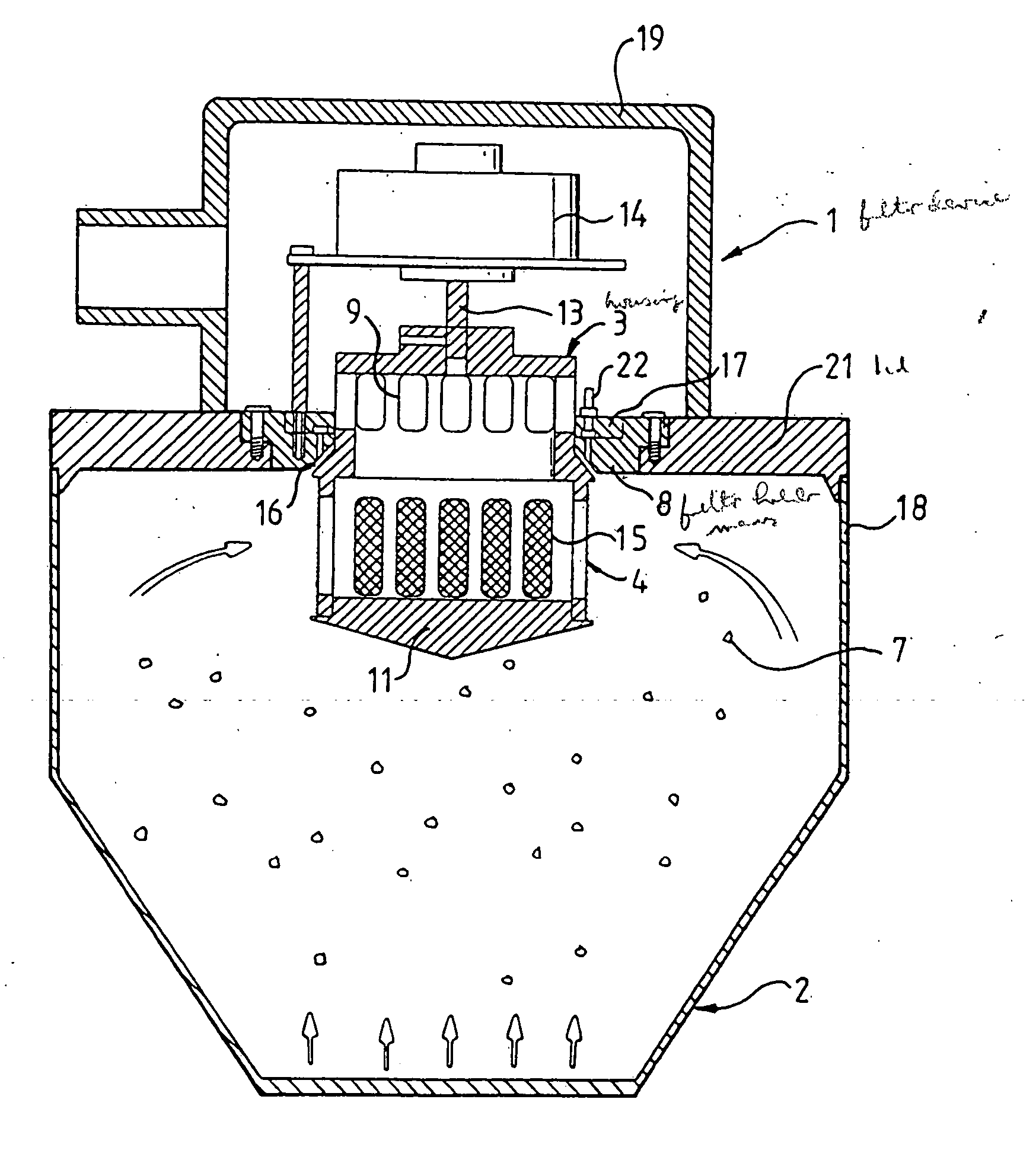
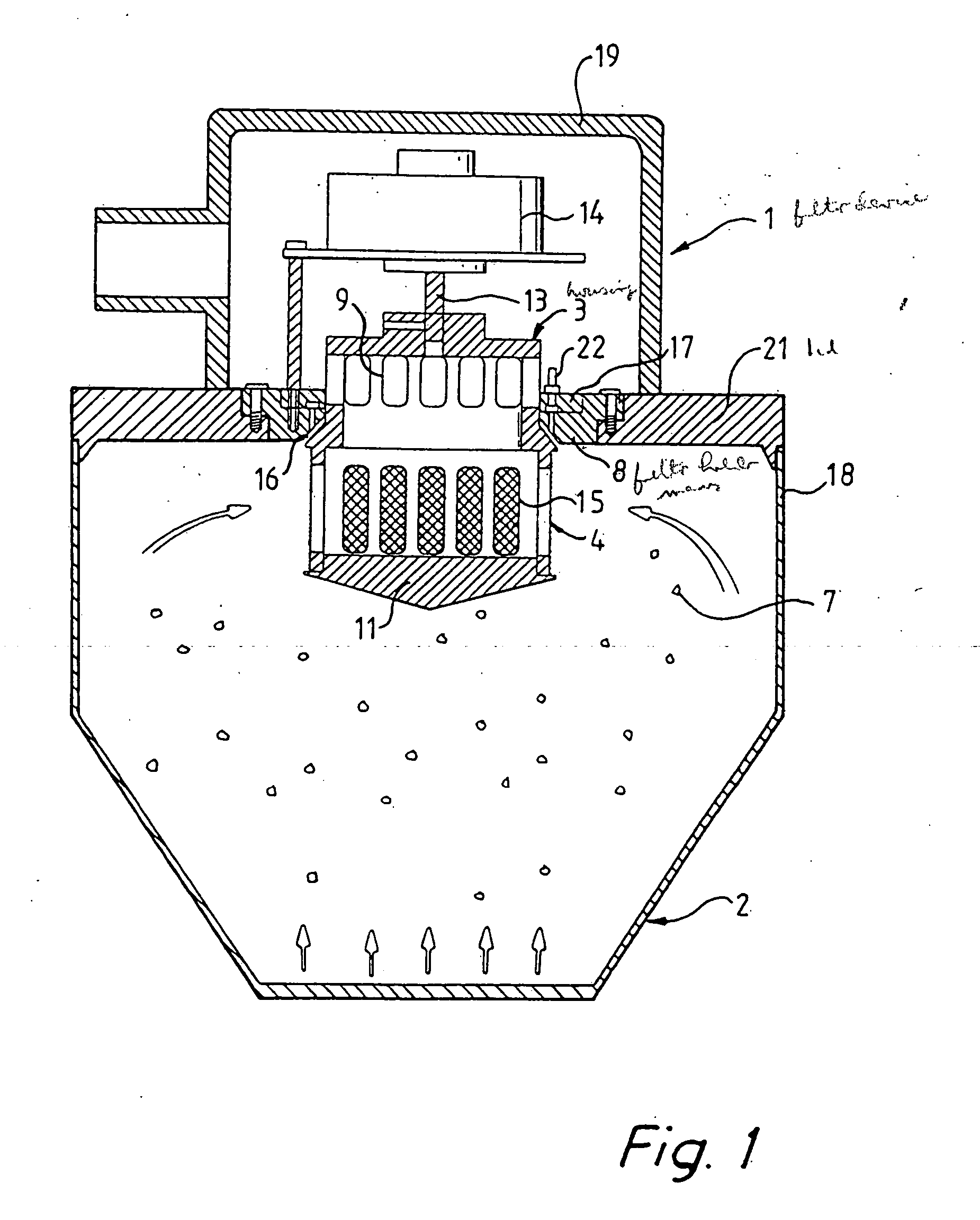
[0032] A preferred embodiment will now be described by way of example only. In FIG. 1, a filter device 1 according to the invention is shown in use in a fluidised bed system 2. In the fluidised bed system 2, particles 7 of different sizes are entrained by the fluid flow (schematically shown with arrows). The filter device 1 comprises a housing 3 arranged in a filter holder means 8 that is supported by a lid 21 constituting the ceiling of a fluidised bed vessel 18. The lid 21 is provided with an aperture to sealingly receive the filter holder means 8. A casing 19 is provided surrounding the outer part of the housing 3, said casing is provided with an outlet passage for leading of the fluid and small particles which have been able to pass the filter device 1.

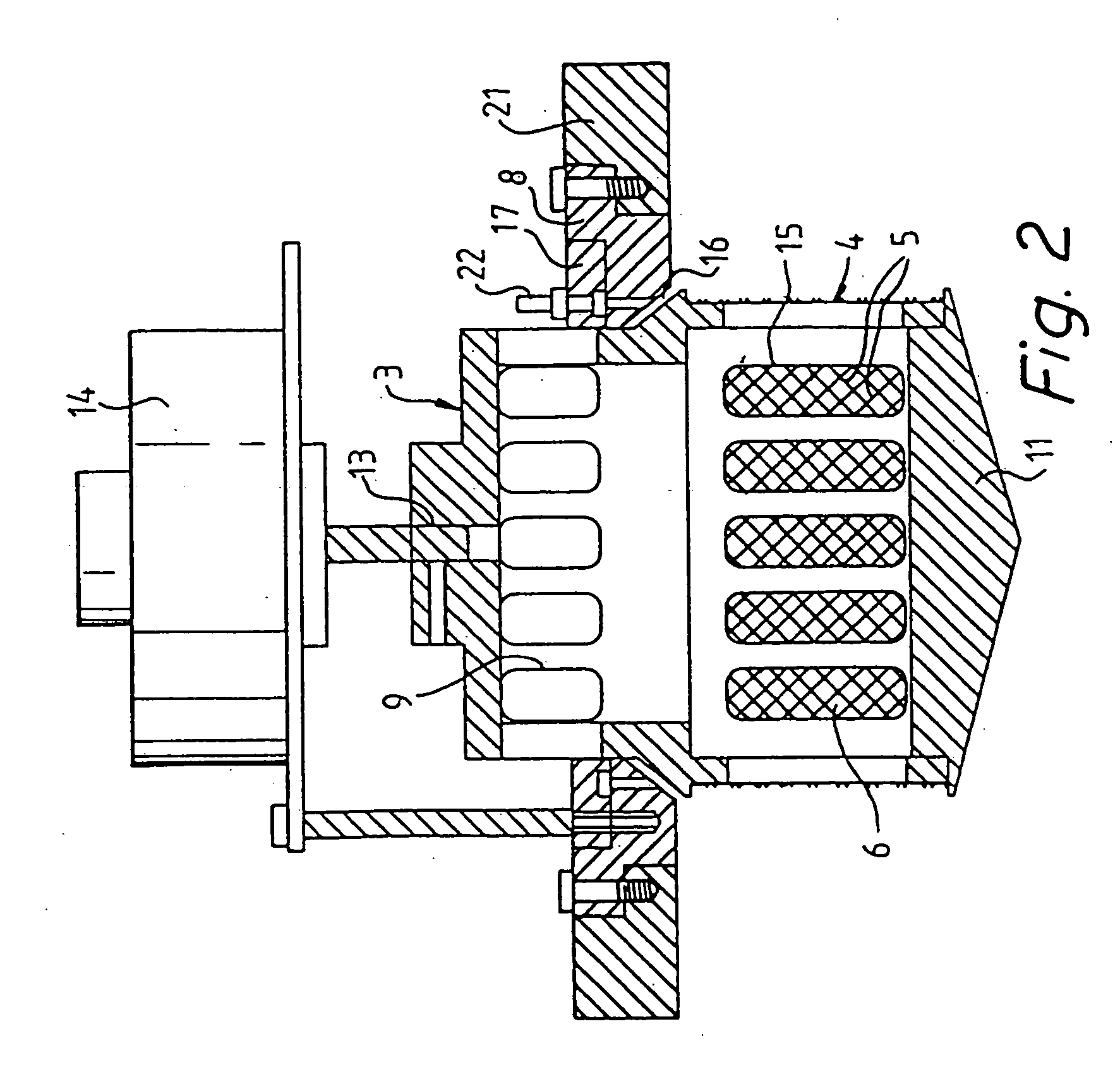
[0033] As could be seen in FIG. 2-3, the filter holder means 8 supports an adjuster element 17 by which the positioning of the housing 3 can be altered. The housing 3 is connected to a motor 14 via connector means 13. Preferably,...


PUM

PropertyMeasurementUnit
Speedaaaaaaaaaa
Widthaaaaaaaaaa
Circumferenceaaaaaaaaaa

Abstract

The present invention relates to a filter device, especially for a fluidised bed system and particularly for use in the pharmaceutical industry, for separating particles larger than a separating grain from an amount of particles in a fluid flow. The filter device includes a housing and at least one filter portion. A part of the housing is mounted for rotational movement, and the filter portion is provided in the housing, whereby the filter portion is movable upon rotation of the housing. The present invention also relates to a method for separating particles using such a filter device.

Description

[0001] This application is a divisional of U.S. patent application Ser. No. 10 / 640,831, filed Aug. 13, 2003, which is a continuation of U.S. patent application Ser. No. 09 / 623,157, now U.S. Pat. No. 6,619,484, which is a §371 of international patent application PCT / SE00 / 01487, filed Jul. 13, 2000.TECHNICAL FIELD OF THE INVENTION [0002] The present invention relates to a filter device especially for a fluidised bed system, particularly for use in pharmaceutical industry, for separating particles being larger than a separating grain from an amount of particles in a fluid flow. The filter device comprises a housing and at least one filter portion. The invention also relates to a method for separating particles using such a device. BACKGROUND ART [0003] In the area of particle formation, coating and granulation it is well known to use different techniques involving a fluidised bed apparatus. Basically, fluidisation is the operation by which solids are transformed into a fluid like state...

Claims


Application Information

Patent Timeline
IPC IPC(8): B07B9/00B01D33/073B01D46/26B07B1/22B07B7/00B07B7/06
CPCB01D29/15B01D33/073B01D35/0276B01D46/0005B01D46/0056B01D46/0073B01D46/24B07B7/06B01D46/2411B01D2275/206B07B1/22B01D33/56B01D46/78
Inventor GLAD, HAKAN
Owner ASTRAZENECA AB
Learn More