
Prefabricated former for constructing underground chamber

a technology for underground chambers and formers, which is applied in the direction of underwater structures, containers, artificial islands, etc., can solve the problems of increasing the time required for construction, posing health and safety risks, and reducing the construction efficiency of underground chambers, so as to achieve easy diversification, increase construction efficiency, and increase the effect of buoyancy

Active Publication Date: 2020-02-13
DUTYPOINT LTD
View PDF30 Cites 2 Cited by
  • Summary
  • Abstract
  • Description
  • Claims
  • Application Information

AI Technical Summary

Benefits of technology

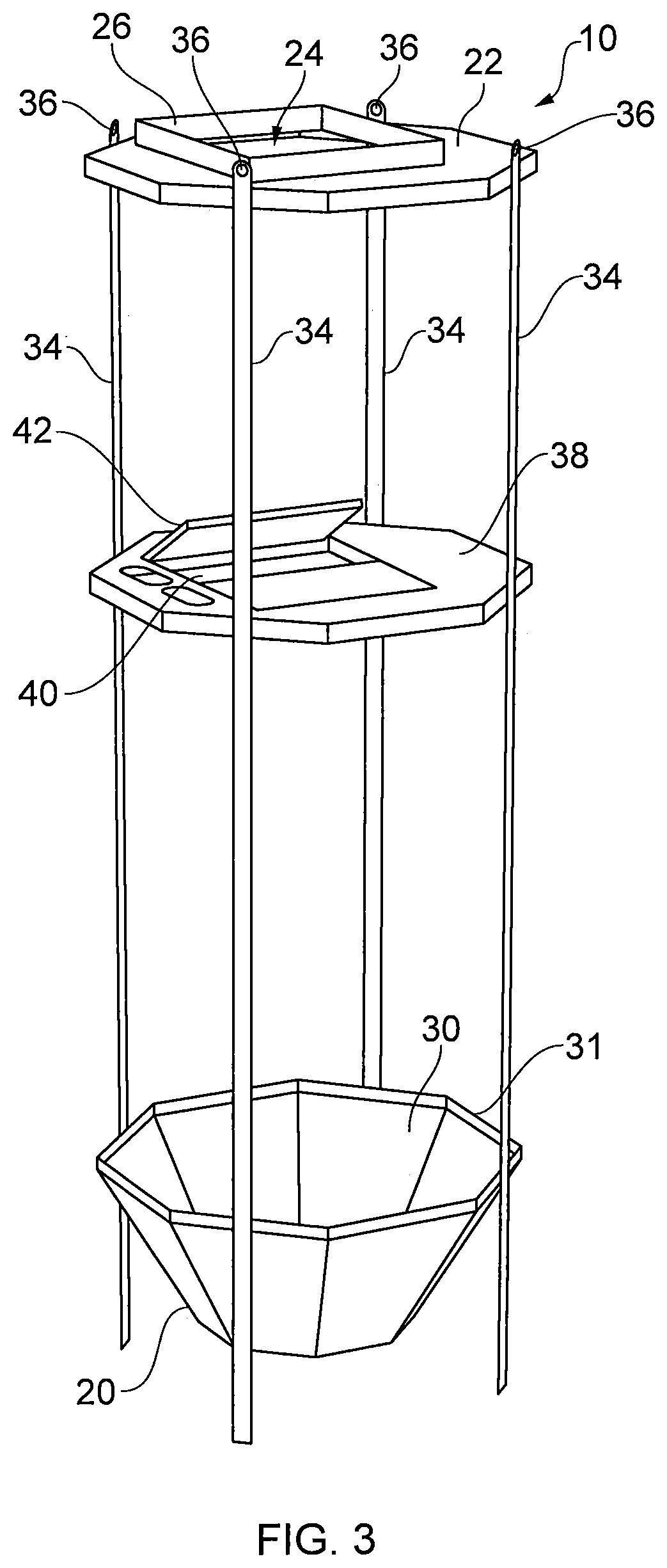
The invention provides a prefabricated former for use in construction, which can be easily adjusted in size and position to counteract buoyancy problems encountered on construction sites. The prefabricated former has multiple vertical support elements that provide structural support around the side wall and leave a clear interior area above the floor for receiving pumping apparatus. The side wall is made of a plastics material and can be designed in the form of a prism to adjust its height. The technical effects of the invention include increased efficiency in construction, reduced buoyancy problems, and improved structural stability.

Problems solved by technology

This requires operatives to work in the excavation for extended periods to assemble the shuttering, posing health and safety risks.
Shuttering assembly also increases the time required for construction.
However, with this solution, a significant amount of groundwork is still required in forming the base and it is necessary to shutter around the tank before pouring the concrete around it.
A further issue with installation of subterranean pump chambers below the water table is that the hydrostatic forces from water surrounding the chamber exert a significant upwards force, or buoyancy.
This may cause even a strong walled chamber to gradually rise upwards from the ground, posing a hazard and potentially damaging other structures.
In many cases, this is not properly considered and the chambers effectively float upwards, damaging pipework, electrical supplies and above ground works.
Also, if the depth of the pump is no longer fit for purpose because it is too high in the ground, the chamber has to be dug up and a new chamber installed.

Method used


Image

  • Prefabricated former for constructing underground chamber
  • Prefabricated former for constructing underground chamber
  • Prefabricated former for constructing underground chamber

Examples


Embodiment Construction

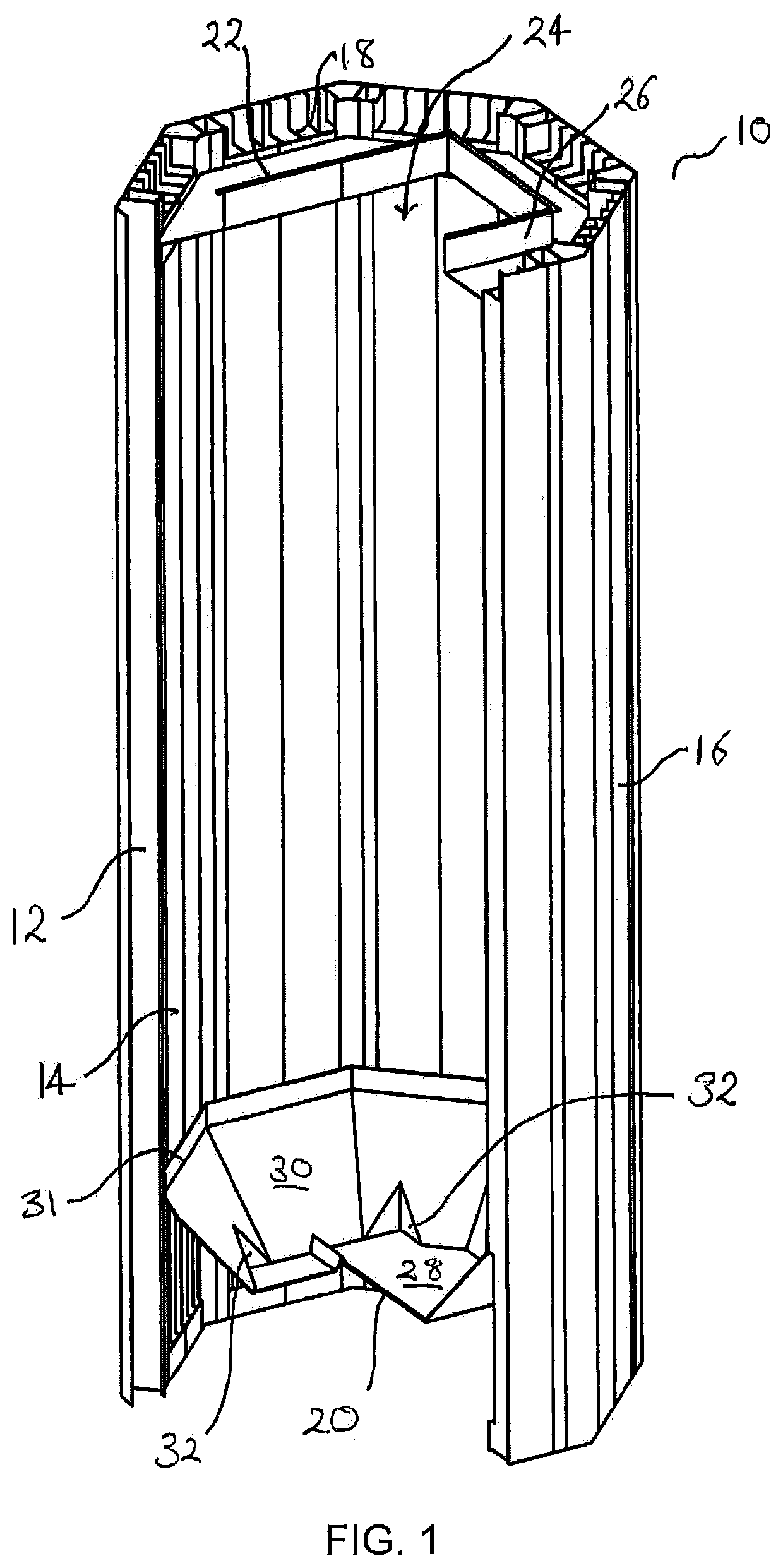
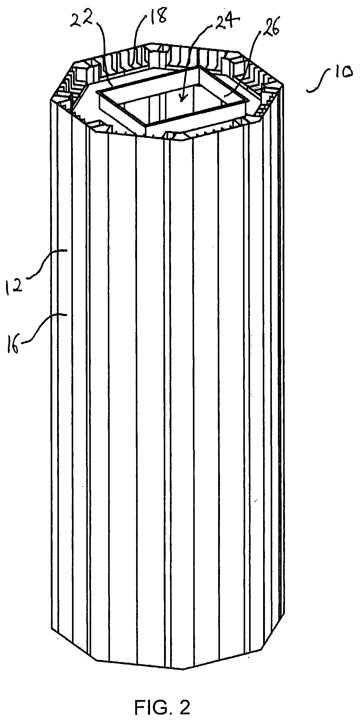
[0042]Referring firstly to FIGS. 1 and 2, a prefabricated former for an underground pump station is indicated generally at 10.

[0043]The former includes a side wall 12. The side wall 12 has an inner layer 14 and an outer layer 16 defining a cavity therebetween. Each of the inner layer 14 and outer layer16 has the form of an octagonal prism, i.e. forming a circumferential and continuous wall, for example, with an octagonal cross section when viewed from above. The inner layer 14 and the outer layer 16 are concentric. The inner layer 14 has a smaller cross-section than the outer layer 16. The side wall is made from plastics and is waterproof.

[0044]The inner layer 14 has a shorter length, or areas of shorter length than the outer layer 16. The continuous inner layer 14 has a lower end, which is situated above an upper end of the outer layer 16. The inner layer 14 has an upper end which is situated substantially below the upper end of the outer layer 16. Alternative inner layer designs a...


PUM


Abstract

A prefabricated former for an underground pump station comprises: a floor former; a plurality of vertical support elements; a side wall secured to and surrounding the plurality of vertical support elements, the side wall having an inner layer and an outer layer defining a cavity therebetween, and an opening at an upper end of the side wall in communication with the cavity for receiving concrete, the side wall extending both above and below the floor former for defining a space above the floor former and a space below the floor former, and an opening being provided between the cavity and the space below the floor former enabling concrete to flow through the cavity and into the space below the floor former; when set, the concrete forming a unitary wall and base.

Description

[0001]The present invention relates to a prefabricated former for an underground pumping station.BACKGROUND TO THE INVENTION[0002]In some areas, ground or sewage water may need to be pumped upwards to main drains for removal. It is necessary to install pumps for this purpose underground and pumps are typically installed in subterranean chambers, where they can be accessed for servicing.[0003]Subterranean chambers for water pumps must be strong to resist the weight of structures above the chamber, and also hydrostatic pressure on the walls and base of the chamber in locations where the chamber extends below the water table. Such chambers are therefore often constructed with reinforced concrete walls and a separately poured concrete base. This construction process requires excavation of a hole, and assembly of shuttering within the hole for receiving the concrete. This requires operatives to work in the excavation for extended periods to assemble the shuttering, posing health and safe...

Claims


Application Information

Patent Timeline
IPC IPC(8): E02D29/12E03B5/04
CPCE03B5/04E02D29/124E03B3/10E03B3/16E03F5/024E03F5/10E21D11/10E02D29/12E03B5/00E03B11/14E03F5/02B65D88/76E02D29/05
Inventor EAGLE, TIMOTHY OLOFFREEMAN, ROBERT JAMES
Owner DUTYPOINT LTD
Learn More