Wire mesh heat shield isolator

Active Publication Date: 2006-10-05
ACS TECH
View PDF6 Cites 47 Cited by
  • Summary
  • Abstract
  • Description
  • Claims
  • Application Information

AI Technical Summary

Benefits of technology

[0008] In light of the foregoing, among the objects of this invention are to provide an isolator, a mechanical bushing, that is a single piece attached to the heat shield, that avoids the problem of unwinding present with a two part device, th

Problems solved by technology

The combustion that takes place in an internal combustion engine of an automotive vehicle produces substantial amounts of heated noxious gas and significant amounts of noise.
The entire exhaust system becomes very hot after a short period of operation due to the high temperatures generated during the combustion processes that produce the exhaust gas and the catalytic reaction in the converter.
Therefore, the use of weldments or other such attachments between the heat shield and the muffler are subject to substantial and repeated forces as the muffler goes through its heating and cooling cycles.
Additionally, the entire exhaust system is subject to significant vibration during use.
Consequently, welded attachments between the heat shield and the muffler are subject to failure.
A

Method used


Image

  • Wire mesh heat shield isolator
  • Wire mesh heat shield isolator
  • Wire mesh heat shield isolator

Examples


Embodiment Construction

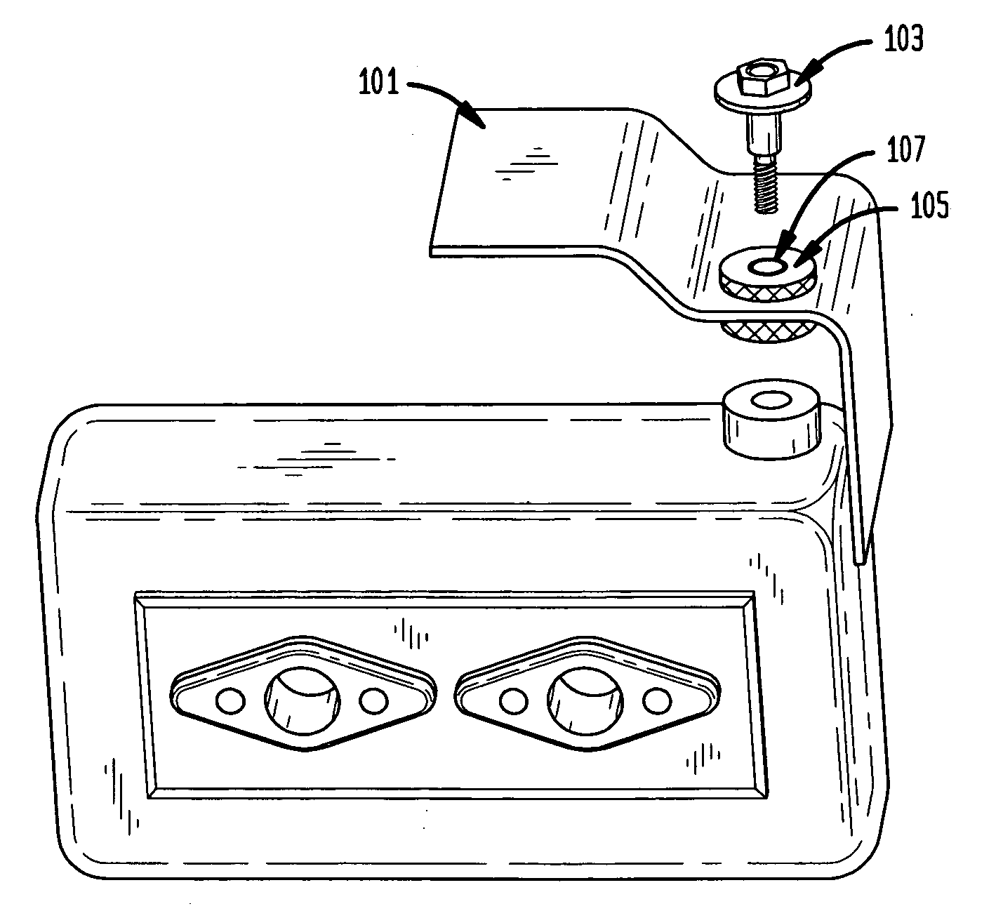
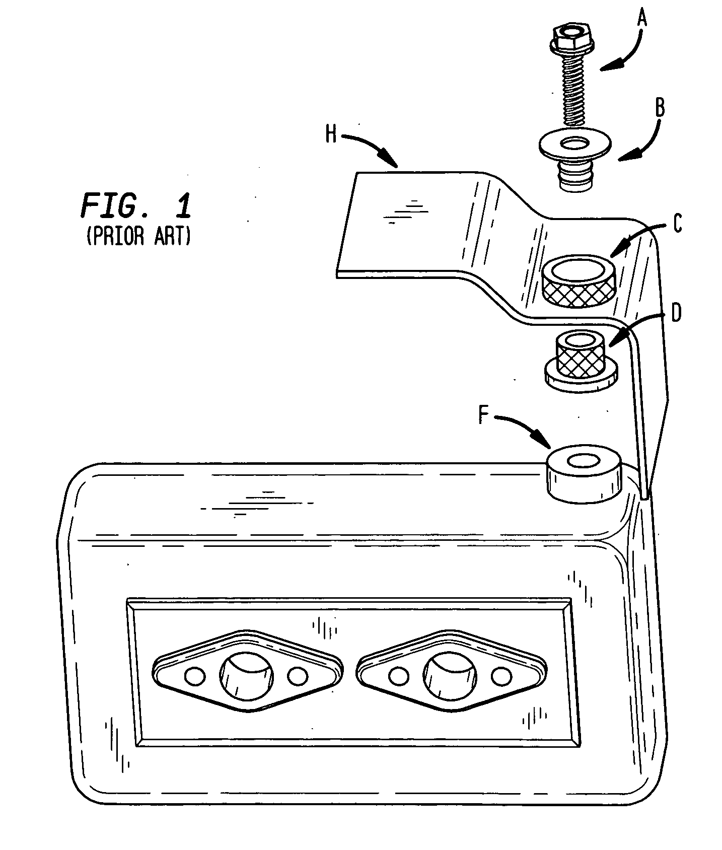
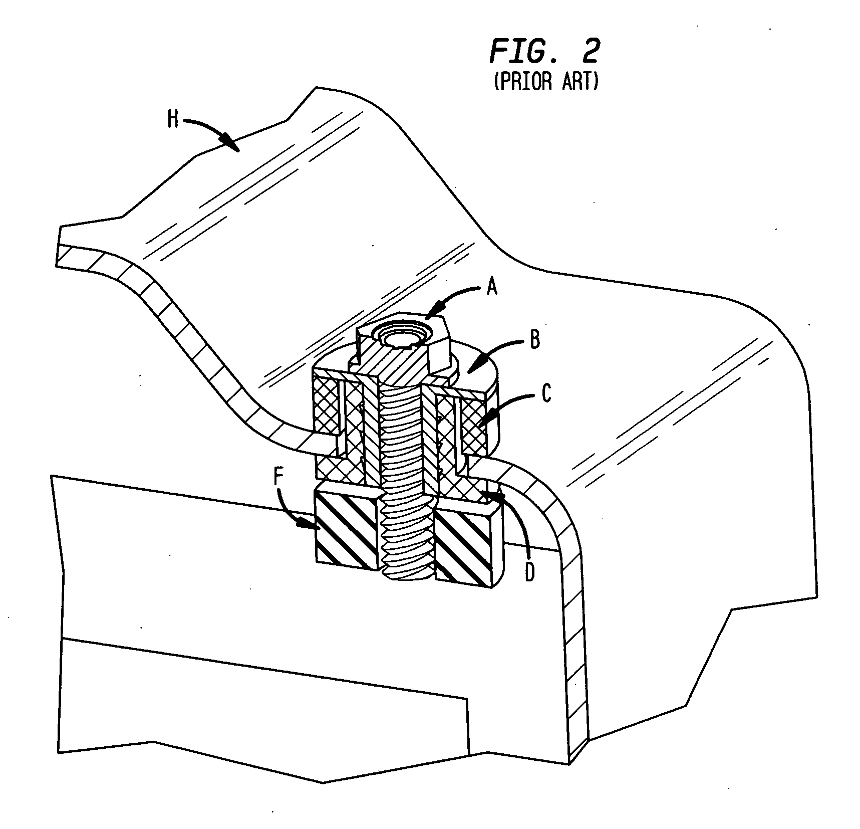
[0018] As explained in the Background section, the heat shield isolator of this invention is a mechanical, heat resistant bushing formed in place of wire mesh.

[0019] Starting with FIGS. 7A-7E, a heat shield 101 (or other substrate) having at least one bore in which an isolator is desired to be formed is positioned in a working area (not shown) and held so that the bore is positioned along the axis of a tool according to this invention. The invention can be used with any substrate, preferably metal, having a bore and able to withstand the compressive force of the forming process. In particular, the tool comprises a lower outer sleeve 703a and an upper outer sleeve 703b, a lower inner sleeve 705 having a lower tamp 706 and a mandrel 707 disposed in the lower outer sleeve and an upper tamp 709 disposed in the upper outer sleeve. All of these parts are coaxial, with those in the “upper” portion positioned on one side of the bore and those in the “lower” portion positioned on the opposi...


PUM

PropertyMeasurementUnit
Lengthaaaaaaaaaa
Diameteraaaaaaaaaa

Abstract

A substrate such as a heat shield for a vehicle is provided with a unitary compressed wire mesh bushing or isolator formed in place though a bore in the substrate. The bushing is formed by supporting an uncompressed or partially compressed wire mesh sleeve, optionally including a grommet or spacer, on a mandrel positioned within the bore; the mandrel is surrounded on either side of the bore by outer sleeves forming a molding cavity on each side of the substrate, and a slidable tamp is disposed in each outer sleeve and moved towards each other to compress the mesh within the bore and provide the unitary bushing.

Description

BACKGROUND OF THE INVENTION [0001] This invention relates to mechanical wire mesh isolators and similar bushings suitable for high temperature use and to methods and apparatus for making the same. [0002] Devices made from knitted wire mesh are commonly used as seals, bushings, seats, and supports in and around exhaust systems for internal combustion engines. In these types of devices, a wire is knitted into a mesh, and the mesh is compacted in a die into a particular shape. Sometimes the compaction is partial, and the partially-compacted structure can be infiltrated with a high temperature resistant material, such as described in U.S. Pat. No. 5,385,873 (the disclosure of which is incorporated herein by reference). At other times the compaction results in a denser article that can be used as a bushing at the end of a catalytic converter, such as described in U.S. Pat. Nos. 4,683,010 and 6,286,840 (the disclosures of which are incorporated herein by reference). Still other devices ar...

Claims


Application Information

Patent Timeline
IPC IPC(8): F16M13/00
CPCB60R13/0869B21F45/16B21J15/046F01N13/1855Y10T29/4992F01N2260/20Y10T29/4994Y10T29/49915Y10T29/4987F16B19/08
Inventor GREENWOOD, GEORGE
Owner ACS TECH
Why Eureka
Try Eureka