
Radiation source for the generation of short-wavelength radiation

Inactive Publication Date: 2006-10-05
USHIO DENKI KK
View PDF19 Cites 21 Cited by
  • Summary
  • Abstract
  • Description
  • Claims
  • Application Information

AI Technical Summary

Benefits of technology

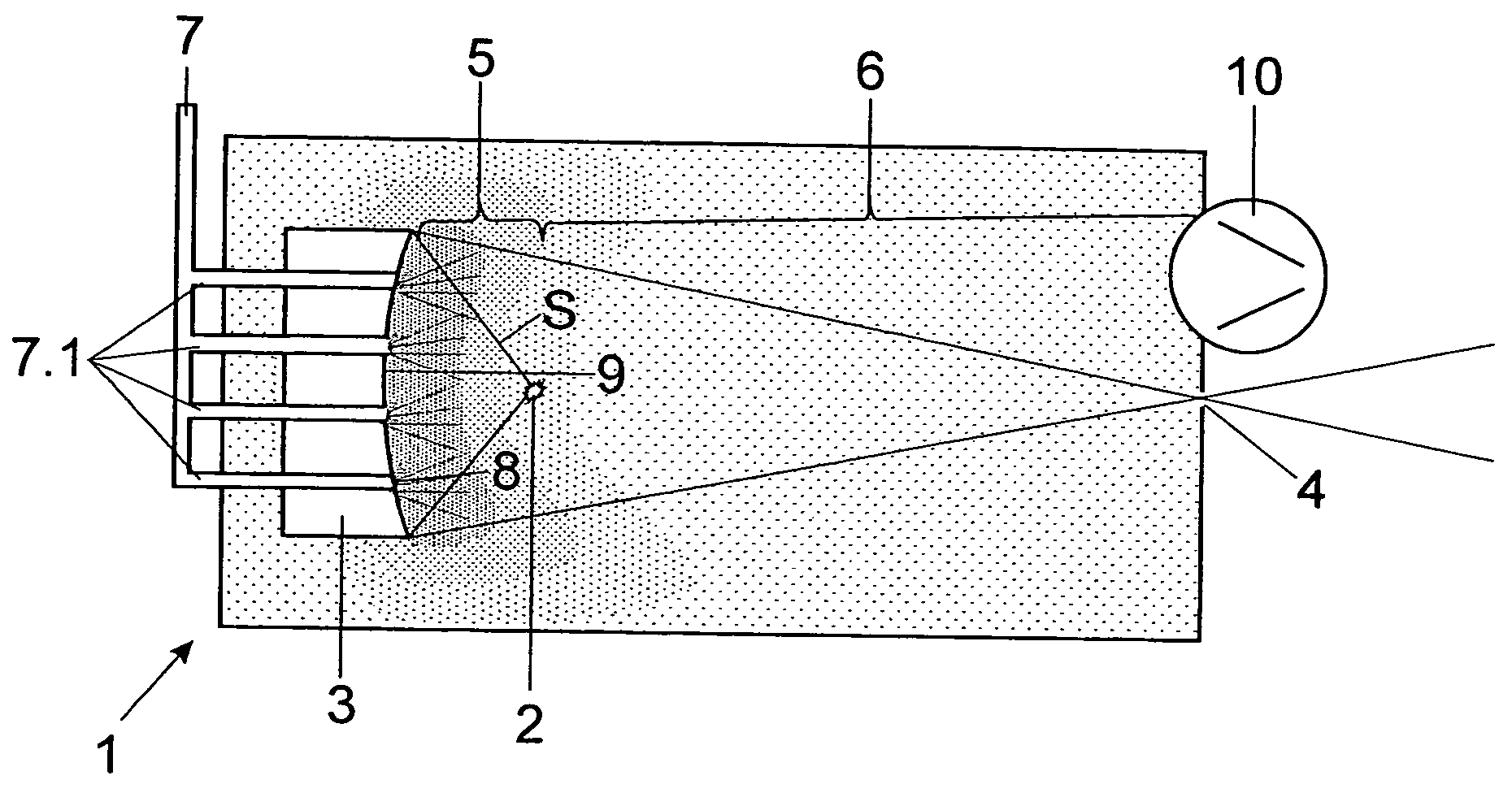
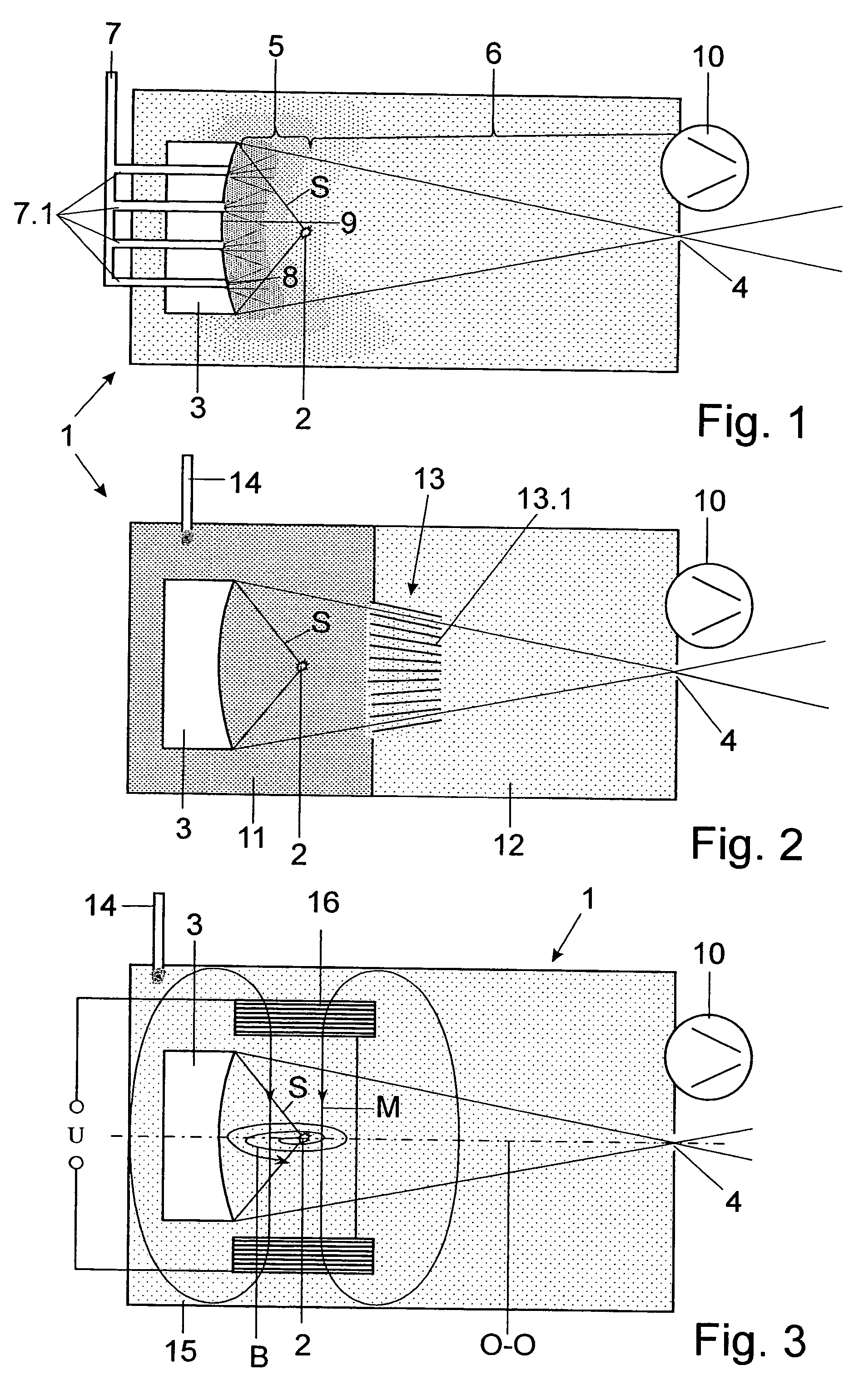
[0010] On this basis, it is the primary object of the invention to effectively increase the protection of the collimator optics by a buffer gas without substantially reducing the radiation transmission.
[0015] It is advantageous when the feed line for the buffer gas has a plurality of partial lines whose gas outlet openings at the surface of the optical element exit in direction of the plasma so that the buffer gas density is higher in the vicinity of the optical element than in the remaining space of the vacuum chamber.

Problems solved by technology

Apart from a desired short-wavelength radiation, plasma-based radiation sources, in particular plasmas which are excited by laser radiation, also emit high-energy particles (debris) which can lead to damage and to curtailment of the life of the optical elements, particularly collector optics, that are provided for utilization of the radiation.
As a result, the efficiency of the radiation source is reduced.
In addition, the conflict between improved protection and increased absorption loss arising when buffer gas density is increased is aggravated by the demand for providing a very large divergence angle of the beam bundle in one direction from the plasma to the collector optics but only a small divergence angle in the opposite direction (from the plasma to the intermediate focus of the collector optics).
A compromise with respect to the buffer gas density which takes into account the requirement for adequate protection while keeping absorption losses within reason is not an acceptable solution because the efficiency of the radiation source is the primary aim of development.

Method used


Image

  • Radiation source for the generation of short-wavelength radiation
  • Radiation source for the generation of short-wavelength radiation

Examples


Embodiment Construction

[0024] The radiation source shown in FIG. 1 contains, in a vacuum chamber 1, a plasma 2 which is induced by laser radiation. The radiation S emitted by the plasma 2 is directed to a radiation outlet opening 4 in the vacuum chamber 1 by means of an optical element which is arranged in the vacuum chamber 1 and constructed as a collector mirror 3. An intermediate focus is generated by imaging the plasma 2 with the collector mirror 3, this intermediate focus being localized in the radiation outlet opening 4 and serving as an interface to exposure optics in a semiconductor exposure installation for which the radiation source, preferably designed for the EUV wavelength region, is provided. The laser and the target flow to which the laser radiation is directed for generating the plasma 2 are not shown.

[0025] Up to the collector mirror 3, the radiation S emitted by the plasma 2 traverses a path on which high-energy particles that are likewise given off from the plasma 2 are decelerated thr...


PUM


Abstract

In a radiation source for the generation of short-wavelength radiation, it is the object of the invention to effectively increase the protection of the collimator optics by a buffer gas without substantially reducing the radiation transmission. A vacuum chamber which encloses a radiation-emitting plasma and is outfitted with at least one feed line and one outlet line for a buffer gas in order to ensure protection against debris for at least one optical element which directs the radiation to a radiation outlet opening in the vacuum chamber has chamber areas with particle deceleration of varying magnitude by the buffer gas. The particle deceleration is greater at least in a first chamber area in which the optical element is arranged than in any other chamber area.

Description

CROSS-REFERENCE TO RELATED APPLICATION [0001] This application claims priority of German Application No. 10 2005 015 274.0, filed Mar. 31, 2005, the complete disclosure of which is hereby incorporated by reference. BACKGROUND OF THE INVENTION [0002] a) Field of the Invention [0003] The invention is directed to a radiation source for the generation of short-wavelength radiation in which a radiation-emitting plasma is enclosed by a vacuum chamber that is outfitted with at least one feed line and one outlet line for a buffer gas in order to ensure protection against debris for at least one optical element which directs the radiation to a radiation outlet opening in the vacuum chamber. [0004] b) Description of the Related Art [0005] Apart from a desired short-wavelength radiation, plasma-based radiation sources, in particular plasmas which are excited by laser radiation, also emit high-energy particles (debris) which can lead to damage and to curtailment of the life of the optical eleme...

Claims


Application Information

Patent Timeline
IPC IPC(8): G01J3/10H05G2/00
CPCG03F7/70841G03F7/70858H05G2/003G03F7/70916G03F7/70908
Inventor HERGENHAN, GUIDOGAEBEL, KAIBRAUNER, THOMAS
Owner USHIO DENKI KK
Learn More