Mount for attaching an electronic component to a rubber article

a technology for attaching an electronic component and a rubber article, which is applied in the direction of tyre parts, tyre measurement, alarm, etc., can solve the problems of difficult attachment of the respective components or transponders to the interior surface of the respective pneumatic tire, inability to monitor the internal tire pressure, and limited service life, so as to achieve the effect of small loads

Inactive Publication Date: 2006-10-05
STAHLGRUBER OTTO GRUBER
View PDF4 Cites 49 Cited by
  • Summary
  • Abstract
  • Description
  • Claims
  • Application Information

AI Technical Summary

Benefits of technology

[0017] The mount according to the invention having mechanical mounting means of the electronic components, in particular a transponder body, is suited for applications in which it is assumed that the service life of the electronic components is shorter than the service life of the respective pneumatic tire or the transponder, or both, is temporarily removed in the course of retreading or another processing step. For example, this can apply to pneumatic tires for commercial vehicles, trucks, and trailers whose mileage is usually several 100,000 kilometers. On account of the strictly mechanical mount, the respectively used transponder bodies can be removed from the main body if an incorrect functional capability of the electronic components is found by the read-outs, for example. Removable transponders have the further advantage that they can be recycled and separated according to predetermined criteria. However, the rather simple design of the transponder bodies is problematic in cases in which, on account of legal provisions or for reasons of product liability, it is requested that the original data of the respective pneumatic tire are assi

Problems solved by technology

A drawback of this transponder type is that only the data stored at the time of a reading operation are available, that is, continuous monitoring of the internal tire pressure, for example, is not possible.
However, such systems are complex and sensitive to the tire loads occurring while driving so that they cannot only cause high cost but might also have a limited service life.
The attachment of the respective components or transponders to the interior surface of the respective pneumatic tire is problematic for all the known transponder systems.
Whe

Method used


Image

  • Mount for attaching an electronic component to a rubber article
  • Mount for attaching an electronic component to a rubber article
  • Mount for attaching an electronic component to a rubber article

Examples


Embodiment Construction

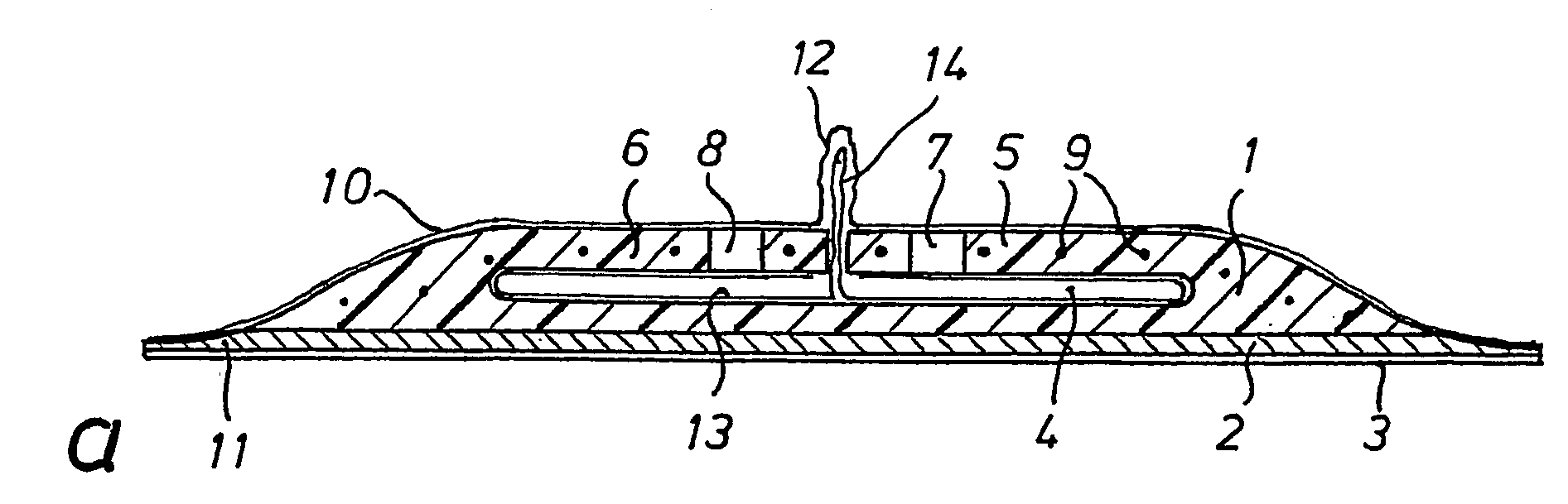
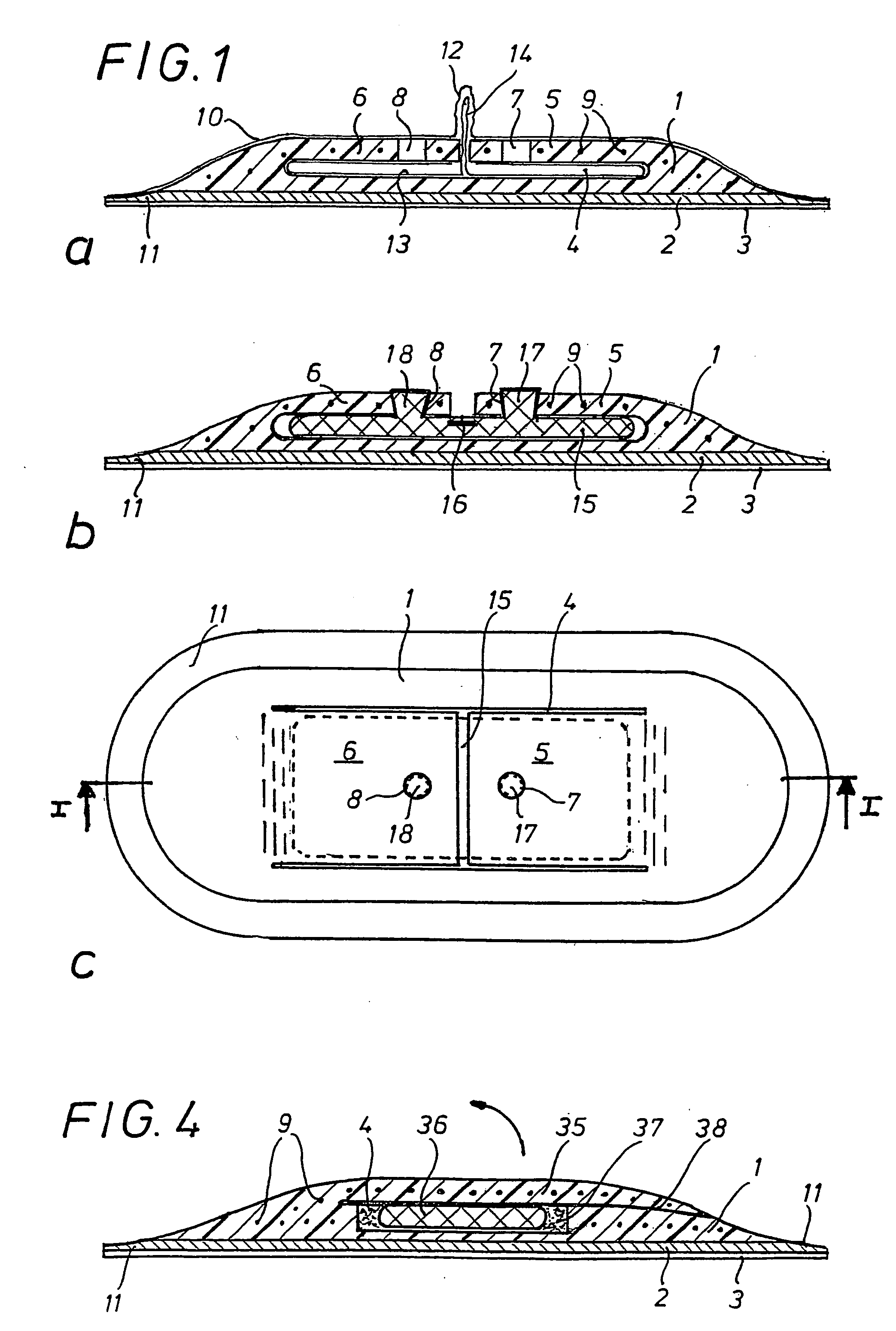
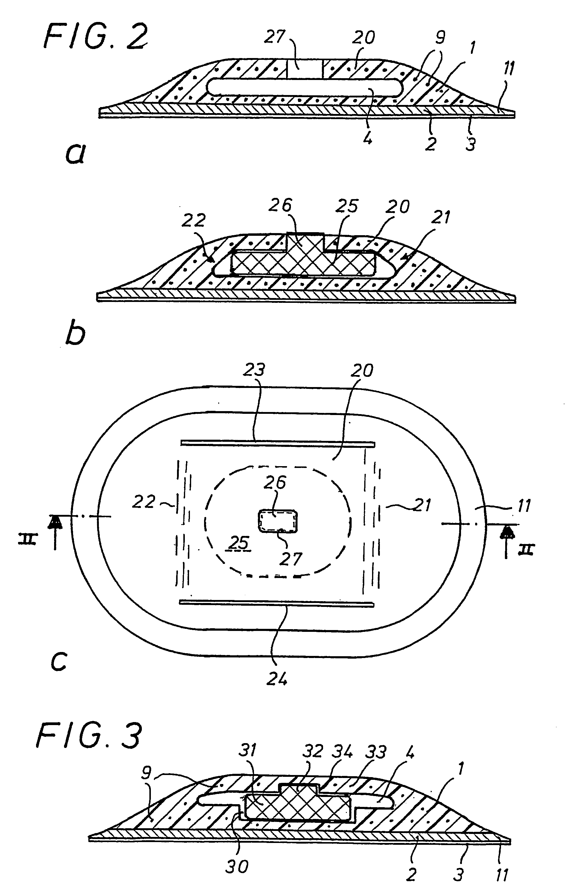
[0032] All the mounts and / or patches shown in the drawing are independent products in which one electronic component each, preferably a transponder body, is inserted and fixed. The mounts shown consist of main body 1 which may have a relative height as shown or even a lesser height. In the embodiment according to FIG. 1, this main body 1 consists of a cured rubber material and has a thickness gradually decreasing from its central portion towards its edge. On the bottom side of the main body there is provided continuous connecting layer 2 made of an uncured, partially cured, or fully cured, rubber material, which is covered by protection layer or film 3 made of a suitable plastic. The protection film can adhere to connecting layer 2. This protection layer prevents environmental changes or influences on a subsequent curing of connecting layer 2 during storage and is pulled off directly before the attachment step.

[0033] In the embodiment according to FIG. 1, large-area recess or gap 4...


PUM


Abstract

A main body for attaching an electronic component, for example, a transponder, on a rubber article, such as a tire, a conveyor belt, or the like. The mount has a connecting layer made, in one embodiment, of uncured, curable rubber material which is covered by an adhering protection film prior to use. A main body made of cured or uncured rubber material is permanently connected with this connecting layer and has a recess for accommodating the electronic component. A cover preferably made of the main body material, serves for fixing the electronic component in the recess in the main body.

Description

BACKGROUND [0001] 1. Field of the Invention [0002] The invention relates to a mount for attaching an electronic component to a rubber article, such as a tire, a conveyor belt, or the like. [0003] 2. Background Discussion [0004] Various systems for marking pneumatic tires for automobiles and commercial vehicles have recently become known, which contain electronically stored and recallable data records for various parameters of the particular pneumatic tire, such as dimensions, manufacturer, type, internal pressure, among others. For example, transponders are commonly used that have at least one chip and one antenna, which are usually accommodated jointly in a shock-proof housing made, for example, of rather hard plastics, rubber or metal. In order to save space and obtain the longest possible service life, it is preferred to use inactive transponders which are only activated by an electromagnetic field created by an outer reader via the installed antenna. A drawback of this transpond...

Claims


Application Information

Patent Timeline
IPC IPC(8): B60C23/00B60C23/04G06K19/04G06K19/077
CPCB60C23/0493G06K19/041G06K19/07745G06K19/07764H01L2924/0002H01L2924/00
Inventor SCHEUNGRABER, PATRICKETZER, LUDWIGREGAUER, EGON
Owner STAHLGRUBER OTTO GRUBER
Why Eureka
Try Eureka