Electronic imaging apparatus

a technology of electronic imaging and zoom lens, which is applied in the direction of lenses, instruments, television systems, etc., can solve the problem of optical system thickness, which is an obstacle to a reduction in the depth of the camera, and achieves the effect of reducing the thickness of the optical system

Active Publication Date: 2006-10-05
OM DIGITAL SOLUTIONS CORP
View PDF5 Cites 18 Cited by
  • Summary
  • Abstract
  • Description
  • Claims
  • Application Information

AI Technical Summary

Problems solved by technology

The greatest obstacle to a reduction in depth of a camera is the thickness of an optical system, notably extending from the most object-side surface of a zoom lens system to an imaging surface.

Method used


Image

  • Electronic imaging apparatus
  • Electronic imaging apparatus
  • Electronic imaging apparatus

Examples


first embodiment

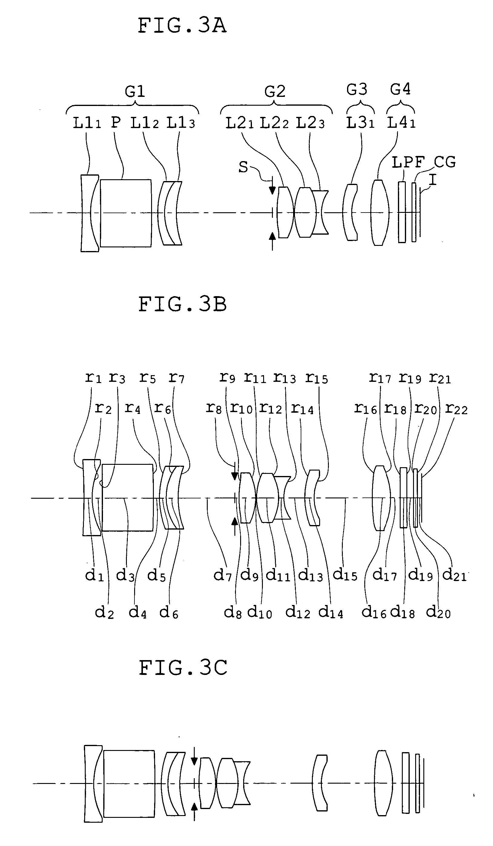
[0113]FIGS. 3A-3C show lens arrangements of the first embodiment of the zoom optical system according to the present invention. FIGS. 4A-4R show aberration characteristics of the zoom optical system in the first embodiment.

[0114] A four-lens-unit zoom optical system of the first embodiment comprises, in order from the object side, a first lens unit G1 with negative power, an aperture stop S, a second lens unit G2 with positive power, a third lens unit G3 with negative power, and a fourth lens unit G4 with positive power. Reference symbol LPF denotes an optical low-pass filter, CG denotes a cover glass, and I denotes the imaging surface of an electronic image sensor such as a CCD.

[0115] The first lens unit G1 with negative power includes, in order from the object side, a first lens L11 with negative power, an optical path-bending prism P, and a cemented lens of a second lens L12 with negative power and a third lens L13 with positive power. The first lens L1I with negative power is ...

second embodiment

[0123]FIGS. 5A-5C show lens arrangements of the second embodiment of the zoom optical system according to the present invention. FIGS. 6A-6R show aberration characteristics of the zoom optical system in the second embodiment.

[0124] A four-lens-unit zoom optical system of the second embodiment comprises, in order from the object side, a first lens unit G1 with negative power, an aperture stop S, a second lens unit G2 with positive power, a third lens unit G3 with negative power, and a fourth lens unit G4 with positive power. Again, reference symbol LPF denotes an optical low-pass filter, CG denotes a cover glass, and I denotes the imaging surface of an electronic image sensor such as a CCD.

[0125] The first lens unit G1 with negative power includes, in order from the object side, a first lens L11 with negative power, an optical path-bending prism P, and a cemented lens of a second lens L12 with negative power and a third lens L13 with positive power. The first lens L11 with negative...

third embodiment

[0131]FIGS. 7A-7C show lens arrangements of the third embodiment of the zoom optical system according to the present invention. FIGS. 8A-8R show aberration characteristics of the zoom optical system in the third embodiment.

[0132] A two-lens-unit zoom optical system of the third embodiment comprises, in order from the object side, a first lens unit G1 with negative power, an aperture stop S, and a second lens unit G2 with positive power. Again, reference symbol LPF denotes an optical low-pass filter, CG denotes a cover glass, and I denotes the imaging surface of an electronic image sensor such as a CCD.

[0133] The first lens unit G1 with negative power includes, in order from the object side, a first lens L11 with negative power and a second lens L12 with positive power. The first lens L11 with negative power is a biconcave lens whose image-side surface is aspherical. The second lens L12 with positive power is a meniscus lens with a convex surface facing the object side.

[0134] The ...


PUM


Abstract

An electronic imaging apparatus includes a zoom optical system having, in order from the object side, a first lens unit with negative power and a second lens unit with positive power, in which lens components having refracting power in the first lens unit are only a single biconcave negative lens element located at the most object-side position and a positive lens component located at the most image-side position; an electronic image sensor placed on the image side of the zoom optical system; and an image processing section electrically processing image data obtained by the electronic image sensor to change the shape thereof. The zoom lens system satisfies the following conditions in focusing of a nearly infinite object point: 0.85<|y07 / (fw·tan ω07w)|<0.97 0.75<|y10 / (fw·tan ω10w)|<0.93 where fw is the focal length of the entire zoom optical system at a wide-angle position, y10 is a distance from the center of an effective imaging surface of the electronic image sensor to a point furthest from the center, y07 is an image height expressed by 0.7 y10, and ω07w is an angle made by a direction of an object point corresponding to an image point, connecting the center of the effective imaging surface of the electronic image sensor at the wide-angle position and the position of the image height y07, with the optical axis.

Description

[0001] This application claims benefits of Japanese Application No. 2005-103053 filed in Japan on Mar. 31, 2005, the contents of which are hereby incorporated by reference. BACKGROUND OF THE INVENTION [0002] 1. Field of the Invention [0003] This invention relates to a zoom lens and an electronic imaging apparatus using the zoom lens, and in particular, to an electronic imaging apparatus, including a video camera or a digital camera, in which a slim design regarding a depth direction is attained. [0004] 2. Description of Related Art [0005] Recently, special attention has been devoted to digital cameras (electronic cameras) as the next generation cameras that are an alternative to cameras for silver halide 35 mm films (135 formats). The digital cameras have come to have many categories in a wide range from a high-function type for business use to a popular portable type. [0006] The greatest obstacle to a reduction in depth of a camera is the thickness of an optical system, notably ext...

Claims


Application Information

Patent Timeline
Patent Type & Authority Applications(United States)
IPC IPC(8): H04N5/262
CPCG02B5/04G02B23/145G02B15/177G02B15/143503G02B15/143507G02B15/144511
Inventor HANKAWA, MASASHISHIROTA, EIJIKAWAMURA, KAZUTERUWATANABE, MASAHITO
Owner OM DIGITAL SOLUTIONS CORP
Why Eureka
Try Eureka